Get ready to make a high-resistance continuity tester pen that runs on a pair of common 1.5V AA batteries. This design is based on an idea from a Chinese website but with a few modifications. So, this handy test light will work with even a quite high resistance between the probes, like up to circa 10MΩ. It uses a couple of jellybean small signal transistors, and has the nice property that power is normally off until continuity detected – a great battery saver!
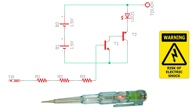
Here is the complete circuit of the handy test light – the standalone continuity tester:
The key components (as used in my prototype) are:
- T1: 2SC1815GR
- T2: 2SA1015GR
- LED1: 5mm Green
- R1-R2-R3: 1MΩ ¼ W
- B1-B2: 1.5V AA battery
What you actually see here is a classic Sziklai Transistor configuration (NPN).
The Sziklai Transistor Pair (Sziklai Darlington Pair) named after its Hungarian inventor George Sziklai is a complementary Darlington device that consists of freestanding NPN and PNP complementary transistors wired together as depicted in our schematic. In principle, it behaves like a single transistor with a current gain equal to the product of the gains of the two transistors.
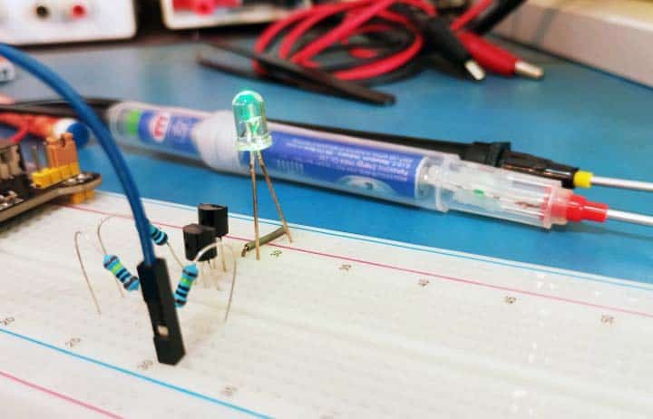
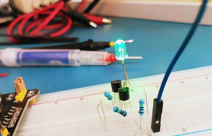
As usual I built a quick prototype on a mini breadboard using through-hole components just to test out the concept.
Although most multimeters today include a continuity tester mode, this handy test light has another significant advantage – it can also be used like a traditional mains tester (one-contact neon test light) to determine the presence of electricity in a device, electric outlet, or piece of bare wire under test (https://en.wikipedia.org/wiki/Test_light).
So, this handy test light is more than just a conventional continuity tester. The built-in battery powered circuitry allows it to perform not only as a continuity tester pen but also as a mains tester to test electricity up to 240VAC.
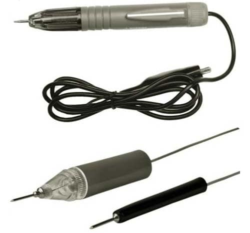
You can build the entire circuit on a perfboard or opt for a freeform circuit version. Either way, the final build should be placed in a perfectly insulated and compact enclosure – for example an old solder tube or glue pen. See a couple of rough ideas below.
And so, to check that an outlet or wire has power, just hold the handy test light by hand, touch the tester tip to the test point (do not touch any part of the exposed tester tip) and finally touch the touch pad/flying lead set at the top of the tester (it is safe to do so). The green LED will glow when the tester tip is in contact with a live point.
⚠ DO NOT ATTEMPT TO CONSTRUCT AND USE THIS TEST LIGHT UNTIL YOU FULLY UNDERSTAND ITS OPERATING PRINCIPLE AND APPLICATIONS. ALSO, DO NOT CARRY OUT REPAIRS OR ATTEMPT ELECTRICAL WORK UNLESS YOU ARE COMPETENT TO DO SO. WHEN IN DOUBT ALWAYS GET HOLD OF A QUALIFIED ELECTRICIAN!
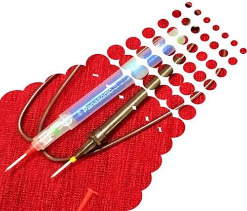
Jumping to a quick conclusion, this post only shares a crude idea of making a multifunction handy test light. The basic concept obviously needs some refinement, so all feedback is welcome. For the final version I will design a cute, printed circuit board and finally enfold the finished electronics in a translucent tube. Also, I recently purchased a set of inexpensive continuity testers for a project I am planning for a future article. Stay tuned…