USB LED Flashlight presented here is a simple do-it-yourself rechargeable flashlight with built in rechargeable cell, cell charger, white light source, and a standard usb interface for overnight charging. Since the design is based on a single rechargeable Ni-MH cell, and onboard voltage booster is added to drive a high-bright White LED. All components used here are inexpensive and easily available for a few bucks.
Component List
IC LM358N x1
IC QX5252F x1
Transistor S8550 x 1
Schottky Diode 1N5819 x1
LED Green x1
LED White x1 (super bright)
NiMH cell 1.2V/1100mAh (AA type) x1
Resistor 22K ¼ w x1
Resistor 10K ¼ w x1
Resistor 1K2 ¼ w x1
Resistor 4K7 ¼ w x1
Trimpot (multiturn) 10K x1
Ceramic Capacitor 100nF (104) x1
Tantalum Capacitor 1uF (105) x1
Inductor 100uH (100mA) x1
USB 'A' male plug x1
Push Switch SPDT x1
Circuit Description
The circuit consists of two equally important sections – the cell charger section and the driver/booster section. In the cell charger circuit, LM358 (IC1) is used to compare the voltage of the 1.2V Ni-MH rechargeable cell (BAT) with a fixed threshold set by an adjustable potential divider (R1-P1). Once the cell is fully charged, IC1 will turn off the charging process and the charging indication. Proper charging of nickel-metal hydride (Ni-MH) cell is a key factor to satisfaction with performance. Although a moderate rate (2 to 3 hour) smart charge method is preferred, here a slow (overnight-type) charging method is used as an economical alternative. Typical charging current observed in the prototype is roughly 80mA. Anyway, the real charging process may vary depending on certain parameters including the rechargeable cell characteristics. Circuit diagram of the charger section is shown below (welcome your suggestions – think on it).
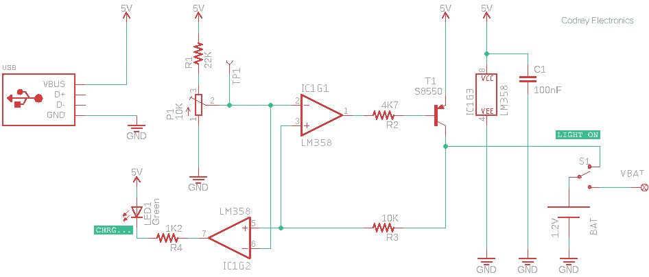
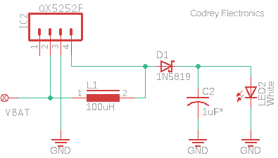
This time I decided to spend some time delving more into the refinements of my earlier designs based on the wonderful Chinese IC – QX5252F. A pretty good addition is a 1N5819 Schottky diode (D1) and a 1uF Tantalum capacitor (C2) to rectify and stabilize the final output. With the 1.2V Ni-MH cell, oscillation frequency was around 160kHz (near 30% duty cycle), and results are quite beautiful and equally usable. With the 100uH inductor (L1) it catered more than 30mA to the white LED (LED2). Later I tested the same setup with a 47uH inductor and marked a felicitous shot up – about 65mA!
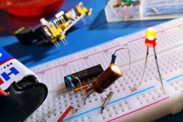
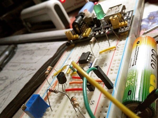
Breadboard Testing of the Charger Circuit
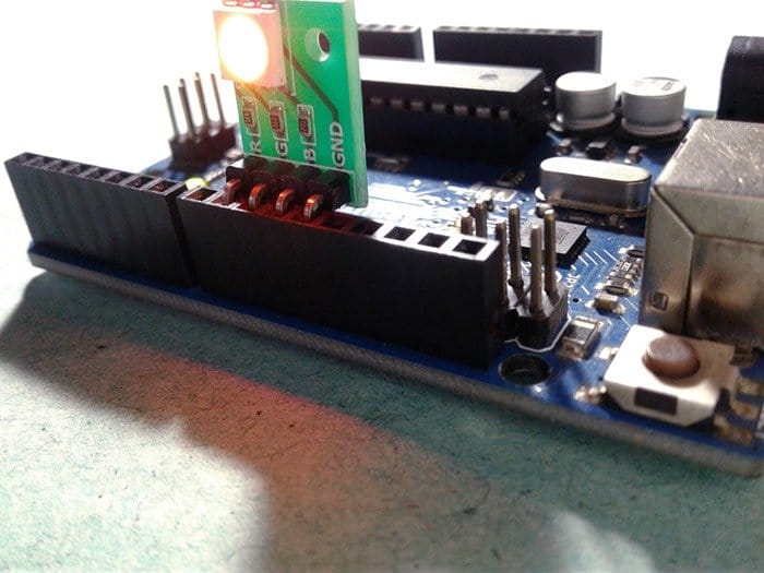
Breadboard Testing of the Driver/Booster Circuit
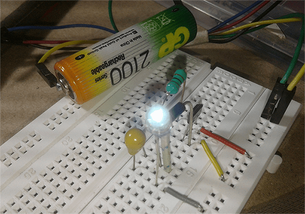
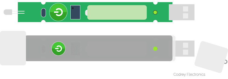
Even though my breadboarded-prototype was briefly tested with a 1.2V/2100mAh Ni-MH cell (it’s only available in my drawer at that time), I still recommend a type with lower capacity (~1100mAh) to cope with the overnight charging mode. Further, this article is a preliminary documentation of the experimentation in progress. Future step will be to mold one nifty enclosure (see my artwork for the end user enclosure).
Unorthodox Charger?
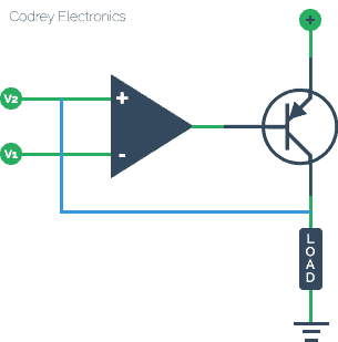
As a part of this usb flashlight project I’d to develop something like a current buffer that could handle currents in mA range to control the battery charging process. As you might observed, in the implemented design, the BJT (T1) works like an inverter and the feedback loop closes in the non-inverting (+) terminal of the op-amp (IC1) rather than ends in the inverting (-) point. The inverting terminal ‘sees’ a reference (threshold) voltage (V1). Look, because of the feedback the BJT is automatically adjusted. For example, if the battery voltage increases more voltage is feedback to the non-inverting input, which controls the BJT just enough to regulate the charging process. From the output current expression it’s clear that as V2 increases the load current decreases. In other words, V2 will be compared with V1, and once the battery voltage level (V2) crosses the threshold (V1), BJT will be turned off to terminate the charging process!
Because the non-inv (+) input is being used as the feedback point, yes, we have a few perplexed matters (will cover this a lot more in future). To save time and keep things moving, just get down to work on the basic design and make timely refinements backed by your practical experience and observation!