It’s only been three weeks since I put together an Arduino Night Light for the kids, and it already made my neighbour’s kids curious!
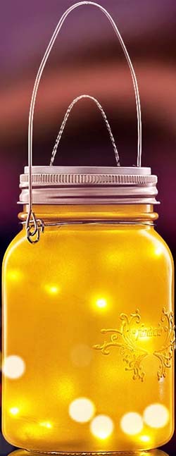
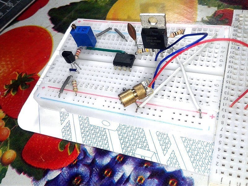
Anyway, long story short, once I had finalized my design thought, I assembled and powered it off my breadboard just to make sure that what I was doing was working (it works). Now it’s just a matter of cramming it into the enclosure. I started off with an old translucent mason jar that I bought once from a craft store. Yes, I then went ahead and enclosed the entire assembly inside the mason jar. Okay, it’s not perfect, but those kids think it’s awesome. Looks shiny!
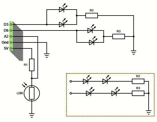
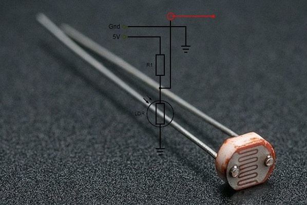
This is the schematic. I have used a few red and yellow LEDs only because after some trial it became apparent that blue LEDs mess with our sleep patterns, and aren’t exactly a good pick for a kid’s night light. I have a mix of green LEDs that I have plucked from old circuit boards over the years, but I do not like to use them here. So only red and yellow at this time!
A list of components is included at the bottom of this post. Now let’s go to the code part – the Arduino Sketch.
int CdSpin = A2; // LDR Input (A2)
int redpin = 3;  // LED Output 1 (D3)
int yelpin = 6;  // LED Output 2 (D6)
int redPinVal = 0;
int yelPinVal = 0;

boolean isLampsOn = false;
int darklevel = 0;
int CdSthreshold = 600; // LDR Output Value (Switch Threshold)
int colourChangeTime = 600000; // 10 Seconds
long lastUpdate = 0;

void setup()
{
  randomSeed(analogRead(0)); // Random Seed (A0)
}

void loop()
{ getdarklevel();
  if (darklevel > CdSthreshold) {
    if (!isLampsOn) {
      LampsOn();
      isLampsOn = true;
      lastUpdate = millis();
    }
    else if (millis() > lastUpdate + colourChangeTime)
    {

      LampsOn(); isLampsOn = true;
      lastUpdate = millis();
    }
  }

  else {
    LampsOff();
    isLampsOn = false;
  }
  delay(1000);
}

int getdarklevel()
{ darklevel = analogRead(CdSpin);
  return darklevel;
}

void LampsOn()
{
  redPinVal = random(1, 128);
  yelPinVal = random(1, 128);

  analogWrite(redpin, redPinVal);
  analogWrite(yelpin, yelPinVal);

}

void LampsOff()
{
  analogWrite(redpin, 0);
  analogWrite(yelpin, 0);

}
Since I’m only using two PWM channels, the hardware setup as shown consists of just four LEDs (two per channel). The LED animations on this one isn’t going to be as elaborate as some commercial kid’s night light models. I basically just want the LEDs to change its brightness level (and hence the display colour) in and out but in a random way. The setup is also sensitive to ambient light so that if the room is well lit, the night lamp would remain off. A 5mm regular photocell (Photoresistor/Cds Cell/LDR) is used here as the ambient light sensor. The code is simple, adaptable, and self-explanatory, so feel free to tweak it.
Better Ideas for LEDs
Arduino’s I/Os have a limit on the maximum current that can be the source or sink and will break if a higher current is demanded. For this reason, it’s important to adjust the amount of current flowing through the I/Os. When using an LED, it’s necessary to connect an appropriate resistor in series with it. It’s possible to find how much resistance is needed by a simple Ohm’s Law calculation (https://www.hobby-hour.com/electronics/ledcalc.php).
You can connect more than one LED (in series or in parallel) to an Arduino I/O as you need as long as you know what you are doing. Arduino UNO’s single I/O pin can provide 40mA and can power two low-current LEDs, but beware you are too close to the maximum current limit of the I/O pin!
You might also consider using one basic transistor, 2N2222 for example, to drive a greater number of LEDs from a steady source of power, too. Moreover, Charlieplexing is another cheerful trick viable for certain LED driver applications (https://www.electroschematics.com/arduino-charlieplexing/).
So, now that I’m done telling you to go for something else to drive your LEDs, go ahead and pick your lamp(s) driver circuit of choice, and create a better night light for kids!
The Light Sensor
In order to detect light and dark, a photoresistor is used in this setup as part of a voltage divider. The photoresistor gives out an analog voltage, as the voltage divider is connected to 5V, which varies in magnitude in proportion to the intensity of the light falls on it. That is, the greater the intensity of light, the lower the corresponding voltage from the LDR will be. This analog signal is then connected to an analog input pin (A2) on the Arduino. The Arduino, with its built-in analog-to-digital converter, then converts the analog voltage into a digital value in the range of 0 – 1023 (for 10 bits). The default analogRead() resolution for Arduino Uno is 10 bits.
The Random Seed
Note that if an analog input pin is not connected to anything, the value returned by analogRead() will fluctuate based on a number of factors, and this is exploited usually to seed the random calculation with the voltage level of the floating analog pin using analogRead(). Since the unconnected analog pin (A0) floats, the value is constantly changing slightly. Anyway, this has to be tested in-depth as it seems simply reading the value of a floating analog pin and using that as the random seed just isn’t the right practice – that might note introduce sufficient variation!
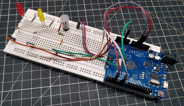
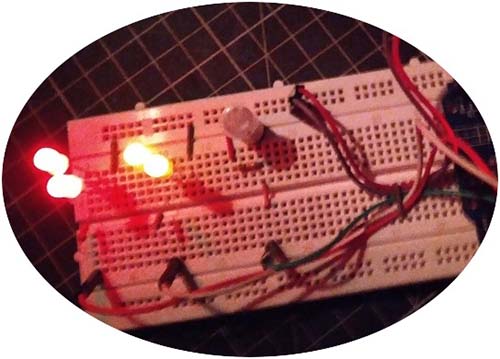
Everything always looks good on paper, so I snapped a few pictures of my breadboard version. Just a proof of concept, that’s it
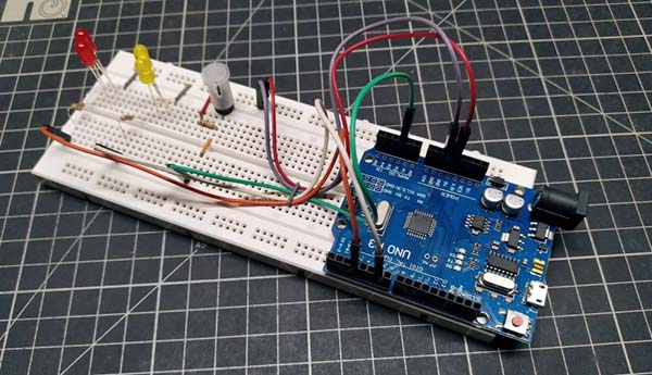
To build a cute night light, you have to arrange all LEDs inside the mason jar in a clever way so that every LED can contribute something to enhance the visual appeal. I realized that, if in the right position, each lamp will render fabulous light effects (even if your setting is not good, it can be attractive if the room is dark enough).
Finally, as you can see, the effect of the breadboard test is not good enough to show up proudly. It looks much better in real, I really love it!
Parts List
So here is, what you need to build one:
- Microcontroller Board : Arduino Uno (R3) or Nano (V3)
- LDR: GL5528
- R1: 10K ¼ w
- R2-R3: (recommended – default) = 240Ω ¼ w
- R2-R3: (recommended – inset) = 150Ω ¼ w
- LEDs: 5mm Red x2 & 5mm Yellow x2 (low-current type recommended)
Extras: Arduino Power Supply/Battery, Mason Jar, Prototyping Circuit Board, etc.