Nowadays minuscule 433MHz RF modules are used in a wide variety of applications that require wireless control, and are very popular among the tinkerers because these modules are very cheap and can be interfaced easily with almost all microcontrollers. I have for some time wanted to hack my RF Remote Control Light Switch I bought from eBay. I have tried to do it by using some old trickeries but failed miserably. Then I discovered that I could use an extra RF receiver to capture the signal coming from the remote with the help of Audacity – the free digital audio editor.
I used a very simple hardware to sniff the RF signals using Audacity on my Win7 Ultimate (x64) Laptop. Well, let me show how can you see what the RF signals look like without having to use a luxury oscilloscope (actually this idea is more easy than using an oscilloscope)!
433MHz RF modules
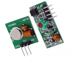
These cheap RF modules usually come in a pair, with one transmitter and one receiver. Specifications of the transmitter and receiver modules are shown below:
RF Receiver:
- Frequency Range: 433.92 MHz
- Modulation: ASK
- Input Voltage: 5V
RF Transmitter:
- Frequency Range: 433.92MHz
- Input Voltage: 3-12V
And, all of these cheap type modules fit these 3 basic pin functions (plus an antenna):
RF Transmitter:
- Vcc: 3V to 12V
- Gnd: 0V
- Data In (accepts logic level digital data, High = carrier transmit)
RF Receiver:
- Vcc: 5V
- Gnd: 0V
- Data Out (logic level digital data, High = carrier present)
When the transmitter data pin is low (L), the transmitter is off, and draws current in uA range. When the transmitter data pin is high (H), it transmits continuous 433 MHz carrier wave, and draws current in mA range. The receiver, when powered up, will crank up its gain until it starts to receive something. When a modulated carrier is received, the receiver will reduce its gain to remove lesser signals, and ideally will then output the same modulated digital data as comes from the transmitter. Since the receiver takes a bit of time to adjust its gain, the data packet transmitted usually starts with a ‘preamble’ before the ‘real’ data to allow the receiver to take enough time for self-adjust its gain before the real data arrives.
Since these are 433 MHz RF modules we can use simple 173mm vertical ‘whip’ antennas, or ‘rubber duck/spring’ antennas with these transmitter and receiver modules (433 MHz has wavelength ~700mm, and a ¼ wave whip of length ~173mm is the simplest antenna).
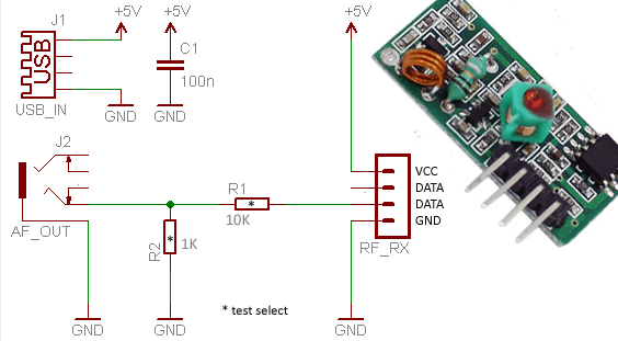
RF Sniffer Hardware
Schematic of the USB-powered RF sniffer is shown below. In the schematic J1 is a standard USB female (type A) socket, and J2 is a standard 3.5mm stereo audio jack with its one channel connected to the input of the sniffer. The circuit is 5V-powered via a USB male-to-male (type A) cable (no other external power source is required). The potential divider components (R1&R2) are used to bring down the RF signal output from the receiver module (RX1) down to a safe level to pump into the audio socket of the computer. You can plug both connectors J1 and J2 (usb cable and audio jack) into USB and LINE-IN sockets of the computer, respectively.
It’s important to use ‘LINE-IN’, not ‘MIC-IN’ socket as it can handle possible larger voltage swings without damaging the sound card electronics. In most laptops, only ‘MIC-IN’ stereo socket is available, however, it’s observed that the MIC-IN socket automatically switches between MIC and LINE level. Anyway, before plugging into the MIC-IN, ensure that it is capable of doubling up as a LINE-IN.
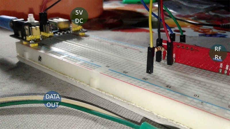
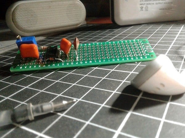
The image below shows my implementation. I used a half- cooked circuit, with everything except the USB power supply (I used a 5V breadboard power supply). The signal/data output is connected to the laptop’s audio input using flexible wires. I didn’t have a 2-core shielded audio cable so I’ve dropped for the time being but that might be the reason I’m getting slightly ‘muddy’ results as you will see afterwards.
RF Sniffer & Audacity
After successful construction of the hardware, connect it to the computer, and open Audacity to proceed (I used my old yet trusted version is 1.3.12 beta). All you have to do is to start recording, press one button on the remote control, zoom in and analyze the signals. Here is a random snap of the waveform produced in Audacity of the captured RF signals. Basically when you press a button, the same sequence is transmitted multiple times and there is a small delay (in ms) before re-sending the same sequence (these timings don’t have to be very precise). With the timings figured out, you can now write down the complete sequence corresponding to the button.
To get started, I picked my ‘2-Channel RF Remote Control Light Switch’, pressed down its ‘Channel A’ button, and immediately started to see data coming out of the sniffer circuit. To read and interpret the data, I zoomed in till I saw individual sample points and measured how many of the pulses are in high (and low) state in the defined period. Here is a casual snap of the process (with little annotation, of course):
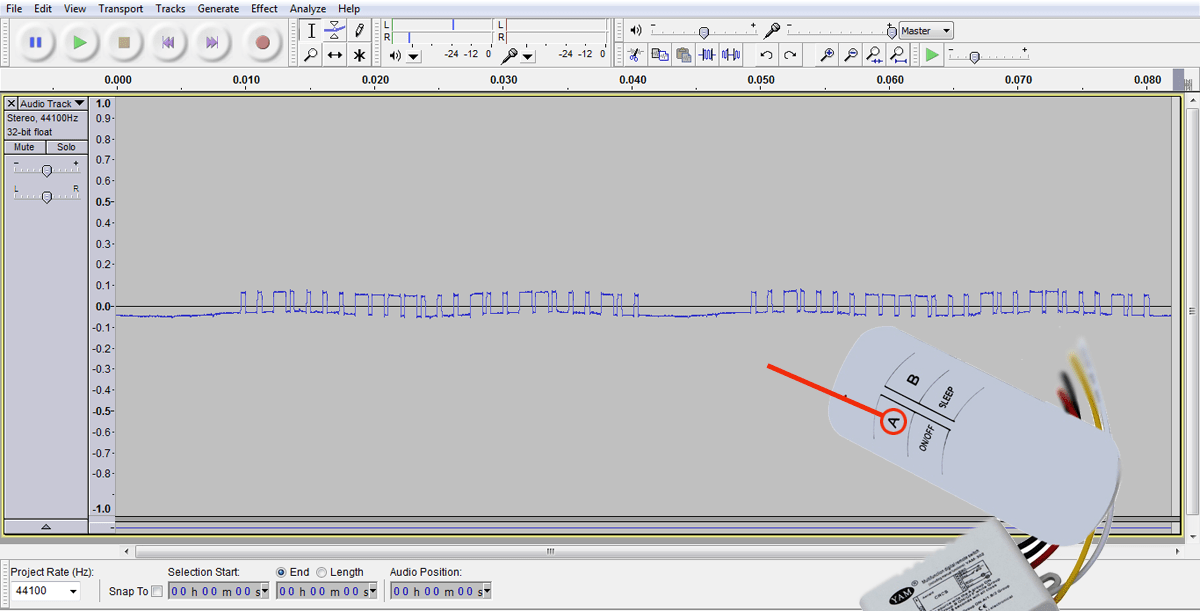
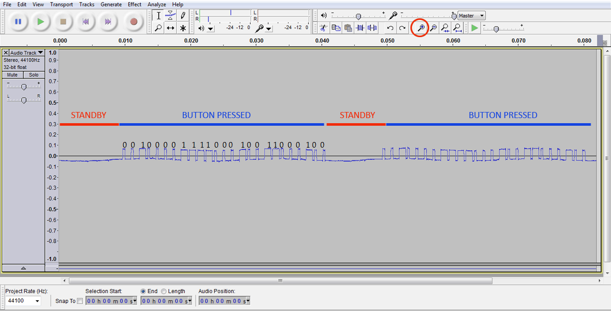
Here, each sequence consists of two types of square waves: a long on followed by a short off, represents a ‘1’, and a short on followed by a long off, represents a ‘0’. Similarly, it’s figured out that the long on or long off is about three times the width of a short on or off. Also, there is small (in ms) delay before repeating the same sequence. With the timings figured out, I got hold of the complete sequence corresponding to the button “A”. It’s a 24-bit code “001000011110001001100010” (2220642 in decimal) with an unexpected “0” at the end (may be an ‘end of message’ indicator).
What’s Next?
Now you have it, a clean shortcut to capture and analyze 433MHz RF Remote Control data. From here you can start the making of your own radio-transmitters as exact replicas of your favorite commercial RF remote control handsets. Just try to capture and decode signals from the transmitter with the help of the simplest setup presented here, and reproduce it using any affordable microcontroller and 433MHz transmitter. Give it a try!!!
I am looking at your schematic which part of the J2 tip is ground and which is signal?
As clearly pointed, J2 is a standard 3.5mm stereo audio jack with its one channel connected to the input of the sniffer. Since only a monaural singal is required, you can use either tip or ring connection together with the sleeve connection for ground.
Hi, thanks for the article!
To isolate the computer’s audio input, you can add an optocoupler.
Sorry for the english, i use the google translate.
Matheus: Exactly. But it’d be better to pick an “analog” optocoupler if available. Thanks!
Hi, I have an RF433 device that transmits at 433.722 Mhz and not at 433.92 Mhz do you know if the pot on the receiver can be adjusted to receive on the 433.722 Mhz signal?
@ Pasquale: As far as I know, we can tweak the transmitter and receiver circuits without much difficulty. Hope the below links will help you to do that. Thanks!
https://www.electroschematics.com/rc-link-ask-environment/
https://steemkr.com/steemstem/@proteus-h/how-a-dirt-cheap-433-mhz-radio-transmitter-for-arduino-works
You know, I have been looking for a week now for everything I could find on this subject. Yours is the BEST.
Will try it as soon as possible, getting parts together now.
Thank you so much for posting it for others
@David Hackenbracht: Thank you for taking the time to comment, and I’m glad you found this useful. If you have any doubts, please leave a message here. Good luck!