This article is about building a little hydrophone that can be used to record underwater sounds. Professional hydrophones used in science world are relatively costly, and even do it yourself ideas feature expensive components. As a first attempt, I decided to make my own version of a little hydrophone by combining cheap (and old) parts resting in my shelf.
Beginning of the construction
Making of my first hydrophone took less than half a day and the final build rendered better upshots while I was testing it on a small fish tank. Following is the tried and tested circuit diagram of my little hydrophone.
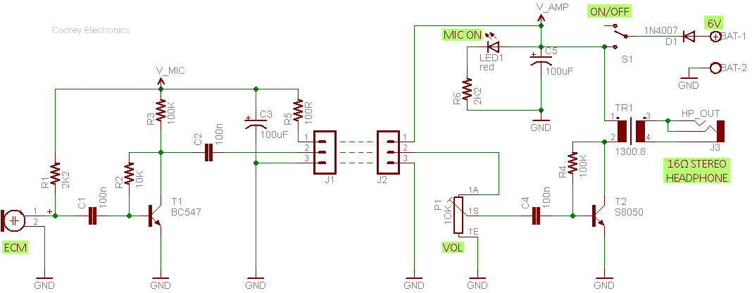
As you can see in the above circuit diagram, the electronics inside is a mere blend of a monaural audio preamplifier and power amplifier. The primary hydrophone component is an ordinary electret condenser microphone (ECM) wired to the input of the audio preamplifier circuit. The pre-amplified microphone signal is then processed further by the audio power amplifier circuit to drive an acoustic transducer (headphone/loudspeaker) connected across its output.
Resistor R1 (2K2) in the audio preamplifier circuit is the microphone (ECM) bias/load resistor, capacitors C1 and C2 (100n) are ac signal couplers, and the remaining resistors R2 and R3 (10K & 100K) are bias components for the preamplifier transistor T1 (BC547). The combination of R5 and C3 (100Ω & 100uF) acts as power supply decoupling components.
The audio power amplifier is again a single transistor (S8050) based tricky circuit that can but deliver decent power to drive one 16Ω stereo headphone (or a small 8Ω loudspeaker). The 1300:8Ω audio output transformer (TR1) is a key component here. Its primary coil is connected with the driver transistor (T1) while its secondary coil is routed to a standard 3.5mm stereo headphone socket (HP_OUT) for connecting an external headphone/loudspeaker. The whole electronics is configured to run by a 6VDC power supply (4×1.5V AA cell in series), the 1N4007 diode (D1) naturally introduces a 0.65V drop, though.
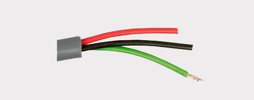
As you might noticed, the red LED (LED1) is a power supply status (MIC ON) indicator, and the 10KA potentiometer (10KΩ audio taper) is the master volume controller (P1). When it comes to the 10K potentiometer, 10K denotes the maximum resistance (10KΩ) of the potentiometer. As far as I know, the letter A or B indicates whether it is a logarithmic (log) taper (A), sometimes called an audio taper, or a linear (lin) taper (B). The 3-pin connectors (J1 &J2) are for secure interconnection between the audio preamplifier and audio power amplifier circuits, preferably through a 3-core low-voltage dc/audio cable (see below).
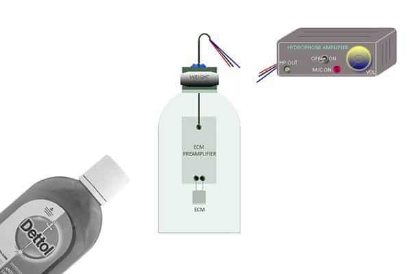
Preparation of the hydrophone container
Initial preparation of the audio preamplifier (microphone preamplifier) circuit portion (on a bit of common veroboard) is necessary to complete the succeeding step that involves potting of the hydrophone container. The audio power amplifier circuitry can be assembled later on another piece of the veroboard.
The first thing is to find a good enclosure that provides enough room to house the populated microphone preamplifier circuit board (ofcourse with the microphone capsule). You can try an empty plastic bottle of the Dettol® antiseptic liquid. Remember to drill a hole in the lid of the bottle just big enough for the 3-core cable to go through. It would probably be easy to apply some kind of silicone sealant outside the lid, to make the hydrophone container fairly strong and watertight. Also make sure you seal off the cable entrance altogether using plenty of silicone sealant/hot glue as it’s the most likely place water will try to enter the container.
Construction of the audio power amplifier
Next phase of the construction process involves the build of the audio power amplifier circuit board. It’s another simple task because you can assemble the low component count circuit on a very small piece of veroboard. With all connections made properly, and after a quick inspection, put the assembly inside a decent enclosure. It would be better to mount all user controls like the power on/off switch, volume control knob, status indicator, etc. on the front panel of the enclosure, and the 3-core cable connector (of your choice) on the rear panel.
Quick lab test method
Plug the 3.5mm TRS connector of the stereo headphone cable into the headphone output jack of the audio power amplifier and turn the amplifier on to medium power level. If the electrical connections have been made appropriately, tapping the hydrophone container will produce an audible sound in the headphone. This simplest test will ensure that the entire electronics is wired properly and is ready for the proposed application.
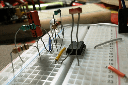
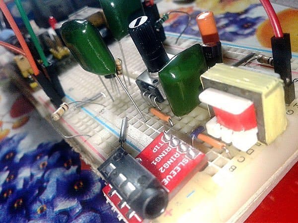
Frankly, my first assembly was on a breadboard. If you don’t know what the hell I’m whispering about right now, have a look at the casual lab snap included below.
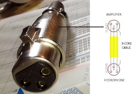
However, after a few successful lab experimentations (thanks to my fish tank), finally I built the hydrophone system exactly as described here, but with an XLR3 male connector at the end of the 3-meter long hydrophone cable. I soldered an XLR3 female connector to the hydrophone input of the power amplifier cable as well to keep the hydrophone system as modular as possible.
What’s next? Now you’ve a simple hobby electronics project of a cheap hydrophone you can use as a demo/ science fair model. Anyway design of the ‘air-chamber’ hydrophone shared through this article has many inherent limits. So try it at first in a home aquarium or a nearby small pond to listen/record the underwater sound. Hope, you’re now ready to experience mystic underwater sounds!