With this article, I’m trying to share one simple idea on how to build a single-key touch pad sensor/switch using a quick and cheap Chinese module. We can easily build a simple touch sensor using the ubiquitous 555 timer chip, but just to be on the scholar side I decided to go with a true capacitive touch sensor TTP223.
The TTP223 is a touch pad detector IC which offers a single touch key. The little chip is designed to replace traditional button key with diverse pad size. Today, we can find several TTP223 modules of distinct types. Below you can see such a minuscule module selected for this project, in particular.
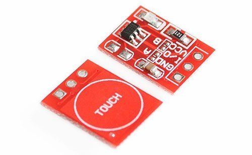
First of all, keep note that the core part of the module is not the far-famed TTP223ASP chip available in SSOP-16 package, but it’s simply an SOT-23-6L package type TTP223-BA6 chip. The TTP223-BA6 chip too has an active high/active low output mode option, and a momentary switch/toggle switch mode option. Pretty great!
Following is the schematic of the aforesaid TTP223B touch pad module (red module) prepared and verified by me. This module has a 2V-5.5VDC (5V typical) operating voltage range.
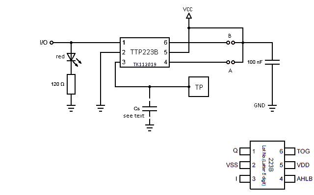
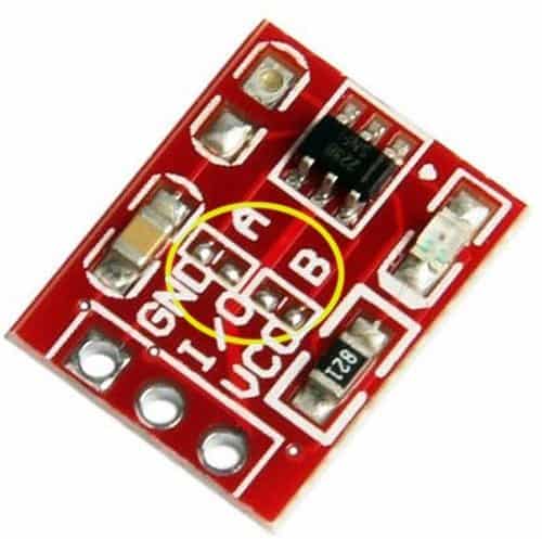
Even though it’s a stamp-sized breakout board, there’s enough options to configure the mode of operation. For example, we can bridge the solder jumper A to select ‘active-low’ output (default = active high), and solder jumper B to select ‘toggle’ mode (default = momentary).
Further, the capacitor marked as Cs is not used in this module but there’s a provision to mount it (see the solder pads).
The capacitance Cs can be used to adjust the touch pad sensitivity. If the value of Cs is small, then the sensitivity will be better. The sensitivity adjustment must according to the practical application in mind. The range of the Cs value is 0~50pF. Here the sensitivity is at its maximum because no capacitor is soldered there. It’s observed that my bare module has a sensing range very close to 5mm!
Next is an insertion on how to use the TTP223B module to control an external device/load. Luckily the module lets us configure its switching action and output status both with simple solder blobs. Therefore we don’t need any complex chips or schemes to go farther. As observed, in active state, output of the module, I tested, delivers about 4V while the Vcc is 5V, and about 2.7V with a 3.3V Vcc.
The circuit diagram shown below can be used to ‘touch-drive’ common power LEDs, hooters, electromagnetic relays, solid-state relays, motors, etc easily. The open-collector configuration of S8050 driver transistor allows safe controlling of various electric loads that require a voltage level higher than 5VDC.
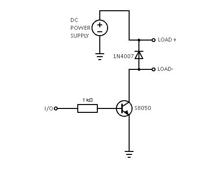
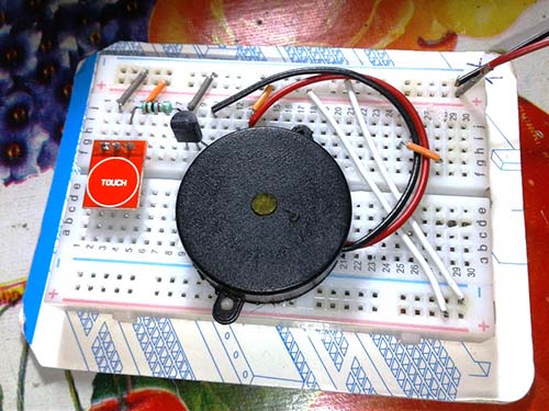
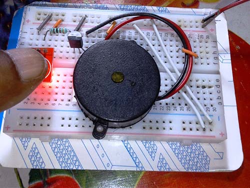
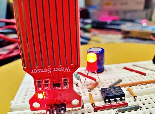
It would be well to start simply, so my initial experiment was with a high-current 5VDC piezo-buzzer. It worked nice! Here’s what I did.
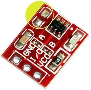
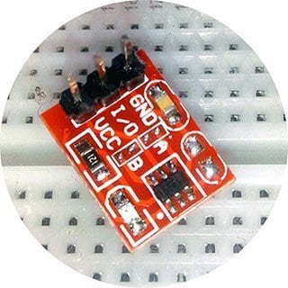
This is a mere close-up of the TTP223B module used for the experiments (thanks to my USB endoscope).
At this point, I had a couple of things left to do. First of all, model a touch-operated star white LED lamp with rechargeable battery backup, and, second, attempt to run the entire build directly from AC230V. Needless to say, the TTP223B module, if combined with the given S8050 driver circuitry, can drive a 1W star white LED well (just use a 5.1Ω/0.5W series resistor for LED current limiting). See the experimental circuit diagram of the proposed power supply section below.
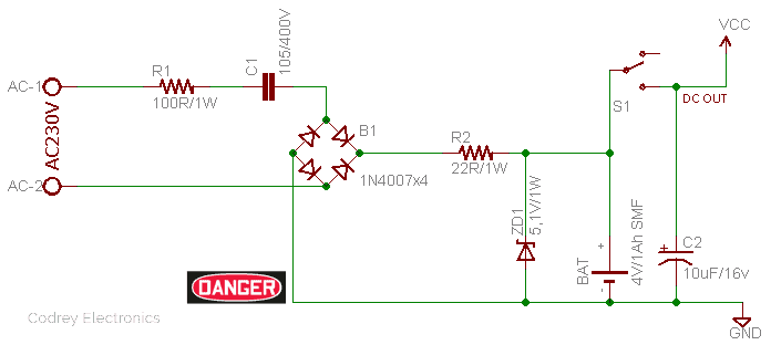
To enclose the ‘fatal’ mains operated touch control light with battery backup, I’d like to choose an acrylic box as it proved to be right for TTP223B based capacitive touch sensors/pads. The proposed design is really easy, it needs a thorough trial run though. Isn’t nice?
Yes, I know you can work totally and definitely without my backing, but in case you need further instructions on how to do that, simply drop your query here in the comments box. Cheers!


Good evening.
I need to install several capacitive sensors to control the lights in a room, because I have 5 pushbuttons and I want to change them by TTP223.
The idea is to control everything with an Arduino Mega 2560, the length of the cables, maximum 15 meters.
The type of cable to use would be UTP CAT5 network cable.
In the tests I have been doing, at the output of the sensors, there is a lot of electrical noise, which causes a malfunction of the system.
Can you help me, please!
Thank you very much in advance !!!