Tilt sensors come in umpteen flavors. The cheapest and most common flavor is the belittled SW-520D tilt sensor module you can find everywhere.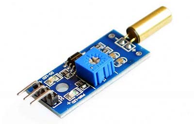
Key component in the demoed module is one SW-520D ‘roll ball switch’ tilt sensor. See its electrical characteristics below:
- Contact Rating: 12v (<5mA)
- Contact Resistance: <10 ohm
- Insulation Resistance: >10M ohm
- Capacitance: 5PF
- Normal Lifespan: 10,0000 cycles
Note that numerous tilt switches with slightly different sizes and specifications are available today. Although they all pretty much work the same, if there’s a datasheet for your typical tilt sensor, you should refer it at first.
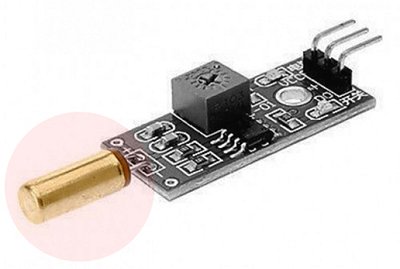
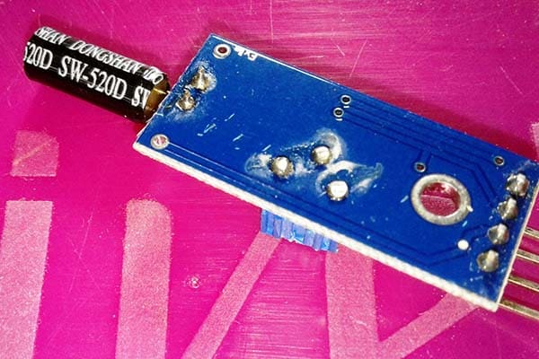
As you can see in the lead image, the module has an onboard LM393 comparator chip to transform the tilt sensor actions into a logic-low or logic-high level final output. But that’s not necessary in many situations so it may be a good idea to use the SW-520D tilt sensor part alone while keeping the circuit board (ofcourse without the tilt sensor) for some other little projects hereafter.
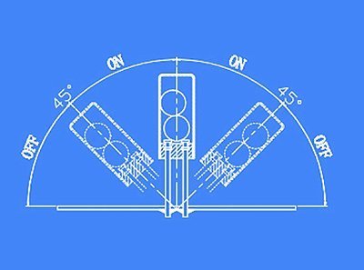
The tilt sensor made by a cavity of some sort of cylindric and a conductive free mass inside allows you to detect orientation or inclination (but not as precise as a dedicated accelerometer). One end of the cavity has two conductive poles. When the tilt sensor is oriented in the aimed direction (see below), the mass rolls onto the poles and shorts them, acting as a switch stroke.
Connecting a tilt switch with another circuit is easy because it’s merely an on/off type switch. Anyway, you can see in the layout below a pull-up resistor and a grounding capacitor – just an RC filter. Actually the optional RC network forms a tricky hardware debouncer to solve switch-bounce issues in some situations where a smooth switching curve with a gradual transition is mandatory. Suggested value for R is 10K, and for C try a value between 100nF to 10uF. Do your maths!
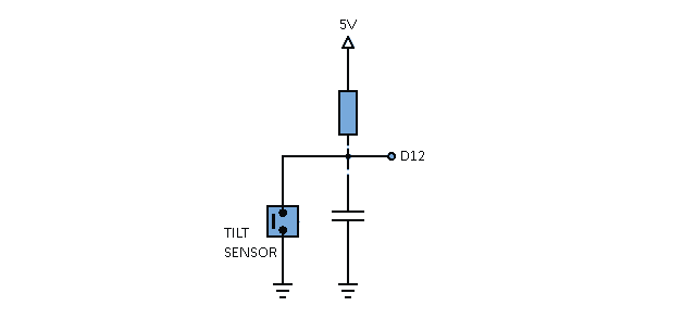
For a quick Arduino tryout, just link the output of the above scheme (without R because internal pull-up is enabled in the code) to digital input 12 (D12) of an Arduino Uno board. The following code will turn on the onboard LED connected to digital pin 13 (D13) of the Arduino Uno board in case of a valid tilt action that lasts for a couple of seconds.
/* Universal Tilt Sensor
 * Cheap SW-520D Tilt Sensor + Arduino Project
 * Adapted Code -- Thanks Adafruit
 * Author: T.K.Hareendran/2019
 * Publisher: codrey.com
*/
int tiltPin = 12; // Tilt Sensor Input
int drivePin = 13; // Drive Signal Output
int driveState = LOW; // Drive Pin Current State
int reading; // Tilt Pin Current Reading
int previous = HIGH; // Tilt Pin Previous Reading
long time = 0; // The last time the drive pin was toggled
long debounce = 1000; // The response time (increase/decrease if necessary)
void setup()
{
pinMode(tiltPin, INPUT);
digitalWrite(tiltPin, HIGH); // Enable the built in pull-up resistor
pinMode(drivePin, OUTPUT);
}
void loop()
{
int sensorstate;
reading = digitalRead(tiltPin);
// If the sensor changed...
if (reading != previous) {
// Reset the debouncing timer
time = millis();
}
if ((millis() - time) > debounce) {
// Whatever the sensor is at, its been there for a long time
// So lets settle on it!
sensorstate = reading;
// Now invert the drive output
if (sensorstate == LOW)
driveState = HIGH;
else
driveState = LOW;
}
digitalWrite(drivePin, driveState);
// Save the last reading
previous = reading;
}
Needless to say, the logic-high level output (~5V) rendered by D13 can be used to control an external load (relay, sounder, lamp, etc) through a proper BJT or MOSFET based low-side switch circuit. Another little home work for you!
As a quick rule of thumb, if you’re switching a load/device on/off, a low-side switch is the recommended configuration. See, in the low-side switch configuration, the driver transistor is connected to ground (0V), and the load is placed between VCC (+V) and the transistor. Since the transistor is switching the path to ground or is sitting on the low side of the load, it’s called a low-side switch. Typically you can use an NPN BJT or an N-Channel MOSFET here.
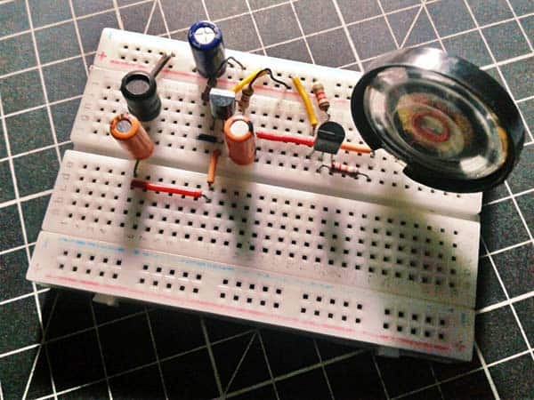
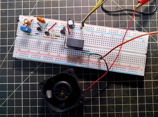
Personally I don’t like to use an Arduino microcontroller for a basic project showing a simple device being turned on and off by the tilt switch. Admittedly it’ll be a clever pick for certain fascinating projects like a tilt sensor-controlled pet water warden, or a poor man’s video game controller, but in other respect, just a crude circuit, like the following one, can do that task neatly.
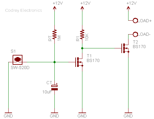
The operation of the circuit is quite simple. When the tilt switch (S1) is activated, the capacitor CT is discharged through S1. This causes the first BS170 mosfet (T1) to turn OFF. This T1 will stay off as long as tilt switch is activated. If the tilt switch is in its OFF state (no tilt) then CT is charged very slowly through resistor RT. Eventually, CT reaches a point where it has charged enough to turn on T1. Note that there’s one 10K resistor (R1) is connected to the gate of the second BS170 mosfet (T2) so when T1 is ON gate of T2 is pulled to low and turns T2 OFF. When T1 is FF, R1 pulls the gate of T2 high, and turns it ON.
You know, if a voltage is applied to a capacitor of value C through a resistance of value R, the voltage across the capacitor C rises slowly. The time constant is defined as the time it will take to charge up to 63.21% of the final voltage value. Here’s an RC Time Constant Calculator http://www.referencedesigner.com/rfcal/cal_05.php. And you may find more about RC Time Constant Derivation here http://www.referencedesigner.com/rfcal/cal_05_01.php
More on Switch Bounce
Switch bounce is a common problem associated with tilt switches. I observed that when the tilt switch is tilted at 45 degree there’re atypical readings caused by the unstable position of the balls inside the tilt switch. I know it’d be damn easy to implement in software but I prefer to clean them all up through hardware debouncing techniques. My first and simplest idea of hardware debouncing is to use an RC circuit (as discussed previously) to filter out rapid changes in the tilt switch signal. Note that another more effective hardware debouncing technique is the use of an S-R Latch to do away with the switch bounces.
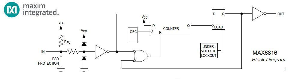
Moreover, after a prolonged Googling I discovered that switch debouncing can also be done by some specialized ICs. The MAX6816 is such a CMOS single-switch debouncer IC that provides clean interfacing of mechanical switches to digital systems. This is the consolidated datasheet of MAX681x switch debouncer ICs https://datasheets.maximintegrated.com/en/ds/1896.pdf
Finally, this is the SW-520D Tilt Sensor/Switch used for my basic experiments. Granted it’s the part of an old module, all the same I still want to go with it!
That is all from me for now. I hope you had fun playing with your tilt sensors. If you have anything to ask feel free to comment down below. Feedbacks are always welcome!
I suggest a low value resistor in series with the tilt sensor. The capacitor discharge current could be very high and possibly reduce the life of the tilt sensor.