If you build battery/usb powered electronics projects, often you’ll be in need of a high-voltage power supply. That is a power supply that has an output voltage higher than that catered by the battery. One way to get a high-voltage output is to build a charge-pump using a few components laying around.
What’s a Charge-Pump?
In reflecting back on what I’d read about charge pumps, I’d like to say that in principle they’re pretty simple circuits. Let’s see quickly how a charge-pump works.
Assume that you’ve a power supply source of 12VDC and you wire two capacitors in parallel and let them charge to 12VDC. Then, what happened if you reconnect them in series? Obviously you’ll get 24VDC! Actually, to make this idea practical, you need switches to do the task of joining the capacitors in parallel, and then in series. It sounds complicated, but turns out simple as there is a renowned circuit called “Dickson Charge Pump” that expends a couple of diodes to carryout some of the switching functions. It’s worth pointing out here that there’re dedicated charge-pump ICs available too – the L7660S from Intersil is one of them.
The Dickson Charge-Pump
The Dickson Charge-Pump, also known as Dickson multiplier, is in fact a simple device where you can multiply the DC voltage many times depending on the number of stages incorporated. Dickson multiplier is intended for low-voltage DC applications, and in addition to the DC input, the circuit requires a feed of two clock pulse trains (in antiphase) with an amplitude swinging between the DC supply rails (see below).
In a nutshell, the Dickson Charge Pump is a clever trick for multiplying an input DC voltage, and is basically a capacitor bucket-brigade, with diodes for flow control, and a switching signal to make it go. For more details, interested readers can go through this Wikipedia article on Dickson Charge-Pump (https://en.wikipedia.org/wiki/Voltage_multiplier#Dickson_charge_pump).
Build Your Own Tricky Charge-Pump
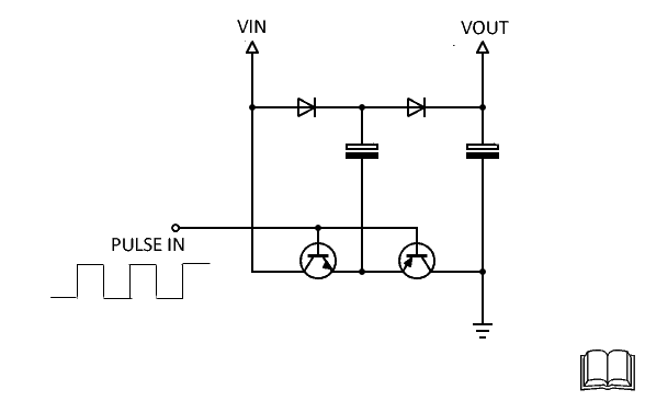
The practical circuit idea presented in this session is merely a tricky charge-pump design, hence it cannot deliver higher currents, but may be a quick solution that helps you to get into various charge-pump projects. Here’s the adaptable schematic of the core part built around a couple of common diodes and capacitors.
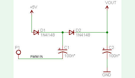
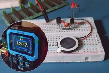
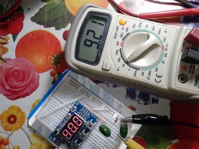
For the PWM input signal, you can use an appropriate single-channel 5V PWM generator circuit. For my quick experiment, I used my dual-channel digital PWM generator module with its first channel output configured to deliver 50% duty cycle, 40kHz, 5V level pulse output, and I got an ‘unloaded’ DC output voltage (VOUT) around 9V (see my experimental setup on breadboard).
Nevertheless, the ‘boosted’ DC voltage available across the output of the charge-pump is as expected. Note that the theoretical output voltage is around 9V because VOUT = (VIN x2) – (VFx2) i.e. (5Vx2) – (0.5Vx2) = 9V, where VIN is the input supply voltage, and VF is the diode’s forward voltage (0.5V typical).
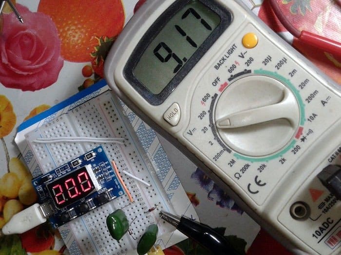
I roughly settled the capacitor value and pulse width modulation signal frequency by trial and error. My first experiment was actually with a 20kHz PWM input (see below). Higher PWM frequency and bigger capacitor value were better, but I didn’t tried anything further!
Perhaps, you don’t have a PWM generator module handy. If so, just upload the following code to your Arduino Uno, and feed the PWM output from its D7 to the simple charge-pump circuit. You should power up the charge-pump circuit by 5VDC (and GND) output coming from the Arduino Uno board. You may also need to change the value of the capacitors from 100nF to 1uF (even up to 4.7uF) to get acceptable results. Anyway don’t kill your lovely Arduino!
Here’s a casual scope trace of the unloaded PWM output from D7.
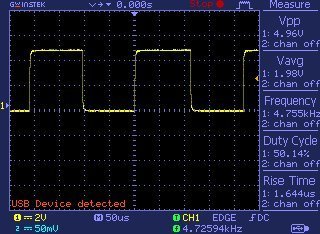
As you can see, the code generates a square-wave close to 5kHz on Arduino PWM pin D7. The duty cycle is set at 50%. Keep note, it’s possible to generate other higher PWM frequencies (~62kHzfor example) by exploiting certain advanced PWM features of Arduino boards.
void setup()
{
  pinMode(7, OUTPUT);
}

void loop()
{
  digitalWrite(7, LOW);
  delayMicroseconds(100);
  digitalWrite(7, HIGH);
  delayMicroseconds(100);
}
More Effective Charge-Pump Thoughts!
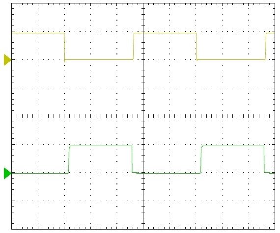
Needless to say, you can add a second charge-pump in the core circuitry ready to be driven by a second PWM signal. But it’s crucial for the charge-pumps to have opposite PWM signals to each other (see my scope capture below). And then, you can add a third charge-pump as well, which is driven by the first PWM signal again. Thus the proposed core setup finally holds a total of 4 diodes and 4 capacitors.
You can definitely see one similar charge-pump project idea based on Arduino Uno, on GitHub https://github.com/tardate/LittleArduinoProjects/tree/master/playground/DicksonChargePump.
And, here’s another superb project https://sites.google.com/site/wayneholder/12-volt-charge-pump
You might enjoy this experiment/tutorial, too https://krakkus.com/charge-pump-tutorial/
That’s all for now. Keep making awesome stuff. Have Fun!