If you are an active cyclist you must become more aware of safety and in particular your visibility to other riders, especially in winter and monsoon seasons. One drawback of your (pleasantly cheap) dynamo lighting is that when the ride stops the lights go out. Fortunately, it’s not difficult to build a ‘smart’ stand light yourself that burning for a few minutes after the bicycle has come to a standstill. Circuit of the bicycle tail light and stand light project introduced here uses a supercapacitor (also know as double-layer capacitor) with a couple of other discrete electronics components. The eventual development of cheap super capacitors seems to be what has led to the stand light revolution in commercial dynamo-based bicycle lighting systems so that charge stored in a supercapacitor can keep the tail/stand light remains on for a few more minutes.
The Circuit
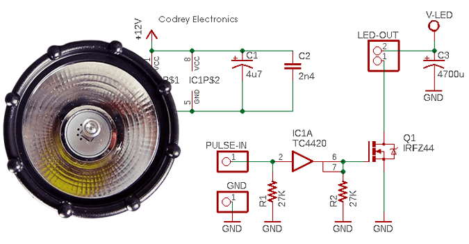
Here’s the tried and tested circuit diagram of the design optimized for common 6V/3W bicycle ‘bottle’ dynamos. In my case, the 6V dynamo gives around 350mA of current while riding at a speed of 15Km/h, and more than 500mA if above 30Km/h. Notably, descending hills at much higher speed raises the output drastically to 7.2V and above.
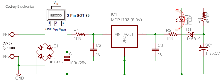
First segment of the given circuit is a 5V edition of the 3-pin linear LDO voltage regulator MCP1703(IC1), driven by the ac output from the dynamo, rectified and filtered by components B1 and C1. The 1uF ceramic capacitors (C2 &C3) are crucial for ensuring good stability. Regulated 5V dc output from IC1 charges the 1F/5.5V supercapacitor (SC1) through components R2 and D1. Finally, SC1 lights up the high-visibility red indicator (LED1) through current limiter resistor R3.
Confessedly, maximum storage of the supercapacitor is not utilized here because of the discrete implementation of the simple charger circuitry (the supercapacitor is charged to 4.7V only). The configuration allows charging currents up to 470mA, though it’s limited down by the dynamo (and the voltage regulator chip) itself. Indicated 470 Ω value for the current limiter resistor results in a stand light time much more than 3-minutes, sure with obtrusive luminance.
The Enclosure
See the water-resistant round enclosure built with scrap parts collected from my backyard.
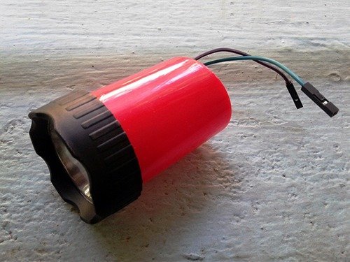
Talking about the electronics, I built the circuit in a slice of double-sided FR4 prototyping board that let me hold the whole assembly inside the enclosure. Little amount of DR. Fixit helped me to make the enclosure waterproof, and finally locked it to the bicycle with a small dc motor metal bracket (commonly used in robotics projects).
Trial Run
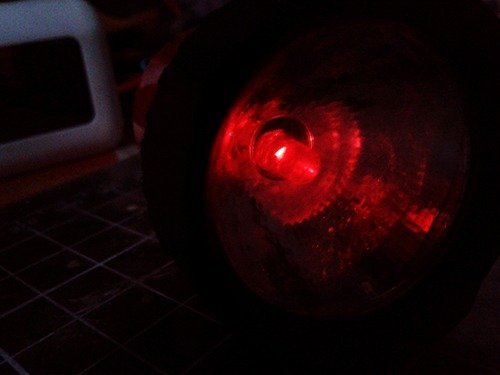
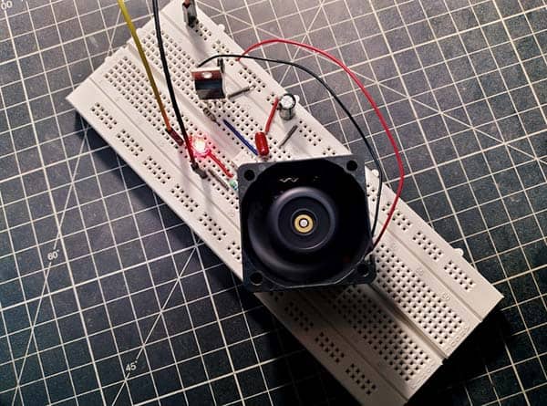
The prototype was first tested with a 6V/500mA ac power supply while it took 30-60 seconds to charge the supercapacitor to the full. Minimum stand light time observed at the time was more than 3 minutes with full brightness, and thereafter another 5 minutes with feeble glow (see below image).
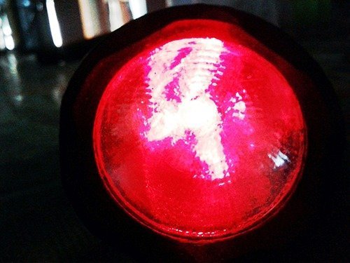
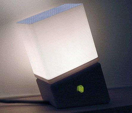
Next in the road test, a few minutes after start of the ride the supercapacitor arrived at maximum charge level, and the stand light remained illuminated for over 3 minutes after the bicycle stopped. The prototype is in use by a neighbor (for visibility test) who kindly sent the night photo. His bicycle already has incandescent dynamo bulbs driven by an old 6v/1.8W bottle dynamo.
Note that the LED used in the prototype is a 5mm diameter super bright red (AlGainP) LED with water clear lens and maximum supply current of 30mA. The particular model manufactured by Kingbright (http://www.farnell.com/datasheets/1701179.pdf ) has a high luminous intensity so a worthy companion on this point.
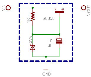
Finally, a discrete replacement circuit for MCP1703 LDO (IC1) shot for those who don’t have enough confidence to handle SMD parts (I still prefer using that chip, though). The proposed series-regulator configuration ensures that VOUT does not exceed 4.9V. Okay, let it ride!
I don’t have enough knowledge to make this myself. Soldering I can do, but the schematic is beyond my knowledge and experience.
Is the a way you could solder this for me?
My daughter has a brand new bike with ans axial dynamo in the front wheel, powering front ans back led lights. But when going to school in the darker winter times, I would love to have her lights burn a little longer at traffic lights to keep her more visible.
I have also read about simple circuits with chargeable batteries, being charged while riding. What are your thoughts about that?
Thank you in advance!!
@ Hans ‘t Hart: It would be more practical if you seek the help of your nearest electronics student/hobbyist who is able to do that.
For your daughter’s riding, perhaps you will need a powerful and reliable dynamo/solar/usb rechargeable bicycle lighting system. Such a headlight can boast a powerful beam and the rechargeable battery fuels the light for a couple of hours.
If you are interested in an advanced do it yourself project, I can post one when I’ve enough spare time (you certainly don’t need to master the theory to build a nice one). Thanks!