Want to keep your laptop/notebook securely? Introduced here is the idea of a simple yet effective laptop/notebook antitheft alarm device with a security cable that fits in the USB port of the laptop/notebook. The security cable can be looped around a table leg or another secure pole, so no one can run away with the laptop while you keep it aside. Incase of any tampering with the security cable (or it’s removed from the port) an alarm will sound to alert the owner. This antitheft device can be used to secure almost all laptops, but especially goof for newer models without the Kensington Lock (K-Lock) hole. The clever design trick will work on almost every laptop in all modes of the machine (on/off/sleep/lock). Smart enough?

Circuit Description
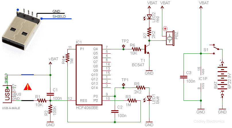
Circuit of the fool-proof laptop security alarm is based on a ‘cheap’ 14-stage ripple-carry binary counter/divider and oscillator chip HCF4060BE (IC1). The entire circuit operates on 9V dc supply from a standard 6F22 9V general purpose battery. In the RC oscillator configuration implemented here, RC components on pin 9, 10, and 11 sets the oscillator frequency (Fosc) which is mainly determined by R3&C2. Oscillator frequency available at TP1 of my breadboard prototype is near 5.3Hz. The blue indicator (LED1) shows the clock pulse activity when the circuit is in ‘active’ state. And, out of the 10 outputs, only the Q4 output (Pin 7) of IC1 is used in this design just for driving a dc piezo-buzzer (PBZ) and a red alert indicator (LED2) through one BC547 transistor (T1). The period of output pulses available at TP2 is around 3sec.
Detection Trick
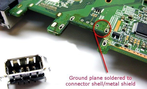
A close inspection of the circuit diagram will tell you all about the clever detection technique used in this antitheft security alarm. As you can see, two connection terminals (SHIELD & GND) of the USB ‘A’ male plug located at one end of the security cable is wired to IC1’s VDD (pin 16) and MR terminal (Pin 12) respectively. When the security cable is plugged into the USB port of a laptop, the ‘pointless’ pair is ‘coupled’ by the internal USB interface of the laptop because usually GND and SHIELD connections of a USB port is gathered together (ground plane tied to connector shell/metal shield) even in cheap laptop motherboards (refer next figure). Naturally, this disables IC1 as its master reset terminal (pin 12) is held at a high-level by the security cable and associated parts. So in ‘idle’ mode there’s no blink or beep alerts. However, if the security cable is not remained intact, the 100K pull-down resistor (R2) enables IC1 so that the piezo sounder starts beeping and the red indicator (the blue indicator as well) begins blinking to raise an obtrusive alert signal until S1 is keyed again by the owner.
Component List
•	IC1: HCF4060BE (ST China)
•	T1: BC547
•	LED1: 5mm Blue
•	LED2: 5mm Red
•	R1&R6: 10K ¼ w
•	R2: 100K ¼ w
•	R3&R4*: 1M ¼ w (see design note)
•	R5&R7: 2K2 ¼ w
•	C1-C3: 100nF
•	PBZ: Active Piezo-Buzzer (5-12V dc)
•	S1: SPST Slide Switch or Key Lock Switch
•	BAT: 6F22 9V
•	Misc: USB A male plug x1, 2-core low-voltage cable x 2 meter, Prototype enclosure x1, etc.


Design Note
HCF4060BE operates over a recommended VDD power supply range of 3V to 15V referenced to VSS (Gnd). The IC contains an easy to use astable followed by a 14-stage binary counter/ divider. Pulses from the astable are passed to the binary counter, and the binary counter outputs are available externally. Pulses at Q4 (pin 7) are divided by 2^4=16 compared with the initial astable frequency (Fosc) while pulses at the final output,O14 (pin 3) are divided by 2^14=16384. The initial astable frequency can be calculated by the formula Fosc = 1/ 2.3xRtxCt, provided Rt << Rx. The practical range of values for Rt (pin 10) is from 10KΩ to 1MΩ, while Ct (pin 9) can have any value from 100pF upwards. Recommended value of Rx (pin11) is x2 (or higher) of the Rt value (any way the last rule is not followed by me here).
Referenced to the presented schematic:
Fosc = 1/2.3 x 1MΩ x 0.1uF = 4.34Hz, and T (Q4) = 1/(4.34/2^4) = 3.68Sec. Got it?
Warning! Get through the USB plug wiring/soldering with utmost care. An incorrect electrical connection will kill your laptop or its USB interface right away. The author (and the publisher) is not responsible for any loss or damage resulting from careless application of this electronic design.
Acknowledgement: Original image of the laptop motherboard was taken from http://www.laptek.net (annotated by author afterwards).

Hello,
Please, I want sound duration to be more than 3s ,like 5 minutes or continuous until a switch is toggled. What modifications do I do?
Or, can you give a schematic based on 555 timer?
Thanks.
Also, by the picture above, does it mean I have to open the Laptop?
Oyeka: Go through this article again. You don’t need to open any laptop. After construction just plug the usb male connector to the usb female port of laptop. That’s enough!
555 is not recommended for this specific design. Yes you can change the sound pattern. I’ll post a note here within a few days. Thanks!