I was following some sellers on the internet, searching a lot more, to get a few difficult-to-get components for some other electronics projects I was planning, and then stumbled haply on a do it yourself kit of one coin cell operated Hearing Aid. Having a few readers (and social media fans) who request such circuits repeatedly, I decided to share an overview here.
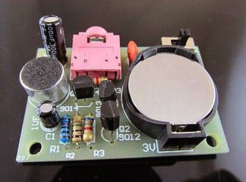
The simple kit packed with all requisite parts comes configured for stereo earphone plugging (actually monaural audio) without a volume control option. As you can see in the photograph below, there’s enough room for mounting the coin cell holder on the component side of the cute PCB.
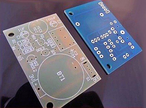
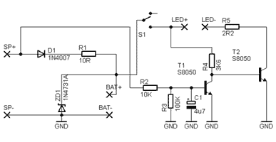
Circuit of the hearing aid is entirely based on 3 transistors, and is supported by 4 resistors and 3 capacitors. Besides there’s a 3.5mm stereo earphone/headphone socket, SPDT on/off slide switch, and a button microphone. Approximate size of the FR-4 A-grade fiberglass PCB is 3.1cm x 4.6 cm. Even though the design seems simple, the high-sensitivity button microphone (electret condenser microphone) accompanying the kit can astoundingly catch faint sounds within 10 meters range. Original circuit diagram provided by the seller is also included here (a curious reader is an author’s delight).
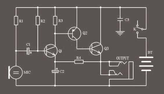
In the circuit, resistor R1 (10K) is the microphone bias resistor while bias resistors R2 (1M) and R3 (6K8) work for transistors Q1 (S9014) and Q2 (S9012). The third transistor Q3 (S9013) drives the plugged earphone (set in parallel by the earphone socket). Resistor R4 (6K8) in the feedback path determines the gain (so the output stability) of the audio circuit. Capacitors C1 (1uF) and C2 (100uF) are integral parts of the audio processing circuitry while C3 (100n) is merely a filter/buffer capacitor. Recommended battery (BT) is the CR2032 type coin cell (3V).
To be frank, it’s not necessary to buy this $2 kit from a China seller because all components are available locally within your easy reach Just use a small piece of perforated circuit board and assemble your own hearing aid by following the given free circuit diagram. You can obviously reverse engineer the design by changing the bias components and by adding a volume control to enhance the entire performance. To minimize the total size of the device further, try to use common “zinc-air” (https://www.mpoweruk.com/zinc_air.htm) hearing aid cells (P13 1.45V PR48) instead of the CR2032 coin cell (https://www.amazon.in/Power-One-P13-Hearing-Battery/dp/B004TED8K2).
Analog insight
There is something you can learn from every circuit and this one is no exception. In principle, the circuit resembles a conventional Direct Coupled amplifier (i.e. with no coupling components between its amplifier stages). In the given 3-stage direct coupled amplifier circuit, output of the first (NPN) transistor is directly connected to the input of the second (PNP) transistor. This selection is done deliberately because the configuration can cancel the rise in the Ic and the variation in β of one transistor by the decrease in the other.
The secret to adjusting the high-gain DC coupled amplifier is the feedback provided by the single resistor in feedback path. The high-value electrolytic capacitor connected at the emitter of the first transistor (Q1) charges and holds its voltage at a fixed value and keep the emitter rigid. Actually output of the third transistor (Q3) is routed back to the emitter of the first transistor by the feedback resistor (R4) so that variations in dc characteristics of the circuit will be countermined most effectively. I will cover this in detail (picking up of very feeble signals while not being overloaded by loud signals), after a couple of weeks (stay tuned to see my own low-cost hearing aid project)!
The 100u is just for DC conditions. There is no volume-suppression provided by this 100u
There is no output when connected to a 3.7v lipo battery and crossed check the connections they are as per schematic. It only outputs noise only when I tap on the mic.
Does it matter which electret microphone we use?
@Yash: The Chinese circuit given here will work. If you are sure everything is correct, check the polarity (+/-) of the microphone once more. Also, it is better to use a high sensitivity microphone in this low-voltage circuit, for example https://www.electroncomponents.com/Tiny-Electret-Condenser-Microphone-Sensitive .
Feel free to come back with your update. I’m watching you. Good luck ✨