The Digispark Attiny85 development board is not only for novices – it’s also a tiny but great microcontroller development board for matured electronicists. Sure, the Digispark board offers 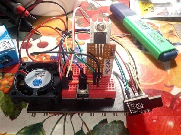 almost everything you need i.e. digital I/Os with PWM, ADCs, onboard linear voltage regulator along with a USB interface for power supply, programming and transferring data. In this article you can see one remarkably simple circuit of a cooling fan speed regulator based on Digispark Attiny85 development board.
Little Fan Governor
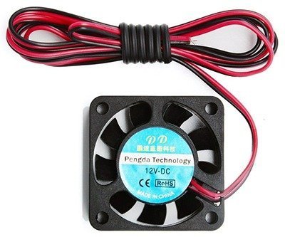
The little fan governor is designed primarily for controlling one (or more) 4010-12VDC micro cooling fans as they’re quite common, cheap, and widely used in small audio amplifier circuits, power supply modules, electronic load testers, etc. Usually such a fan draws 100-120mA of current at 12VDC and delivers a moderately strong current of air without making very much noise.
Digispark Code
/*
 * DC Cooling Fan (12V) Speed Controller v1
 * PWM speed Control with Digispark Attiny85 Development Board
 * Author: T.K.Hareendran/2019
 * Publisher: codrey.com
 */
int potPin = 1; // Potentiometer Input to Pin P2 (See, ADC1 is connected to digital pin 2)
int potValue = 0;
int pulse = 1; // Pulse Output from Pin P1 (See, there's an onboard LED connected to digital pin 1)
/* Hardware PWM Frequency @ P1 = 504Hz :: Digispark @ 16.5MHz */
void setup() {
pinMode(pulse, OUTPUT);
 }
 void loop() {
 potValue = analogRead(potPin);
 analogWrite(pulse, potValue/4);
 delay(10);
 }
More on PWM
As you might guess, pulse width modulation (PWM) idea is used here to regulate the speed of the cooling fan through a ‘user-control’ potentiometer. With the PWM technique, that is to say modulation of pulse width, it is possible to gradually turn on the cooling fan with continuously adjustable speed roughly from 0-100%. The beauty of a PWM controller is that it controls the output load without burning excess energy (energy from the power supply is used only as much as required to get the desired speed). Anyway, in principle, some energy will be lost in the circuitry due to certain factors, but not that much!
The Digispark based PWM controller features almost 0-100% pulse width regulation using a standard potentiometer, while keeping the oscillator frequency relatively stable. The given hardware (and software) configuration will give a frequency about 504Hz. Below you can see random oscillograms when scope was hooked to the unloaded pulse output pin (P1) of the Digispark PWM generator.
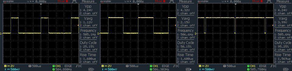
As you can see from the oscillograms, a 25% duty cycle signal is on for 25% of the wavelength and off for 75%, while a 95% duty cycle signal is on for 95% and off for 5%. Since these signals are sent out to the cooling fan at a high enough frequency, the ‘pulsation’ has no serious effect on the cooling fan.
It’s assumed that most readers have got a basic understanding of PWM speed controllers. Just to summarize briefly, a PWM speed controller uses one fixed-frequency oscillator to drive the power switch and transfer energy from the input to the output. The drive signal employed is constant in frequency but varies in its duty cycle (the pulse width is adjusted based on operating condition).
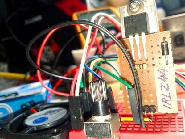
Hardware Setup
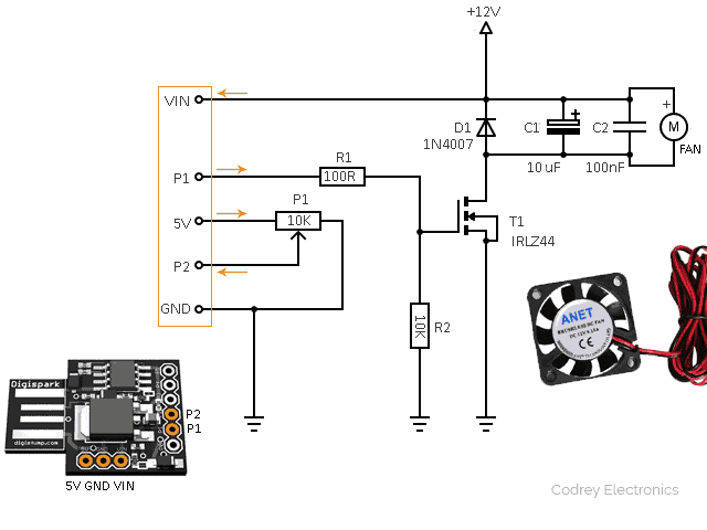
Say thanks to the extremely easy hardware configuration. The hardware hook up is simple – the ‘speed controller’ 10K potentiometer is connected across the regulated 5V and GND rails with its wiper wired to the first analog input (P2=ADC1) of Digispark. The second PWM output (P1=PWM2) of the Digispark board is routed to one IRLZ44 logic-level power Mosfet (T1) through a pair of resistors (R1&R2). The final (traditional) components (D1-C1-C2) connected in parallel with the cooling fan are included purposely to suppress potential noise, counter-emf, etc.
Side-Look
As regards the theory, it may be worthy to note out that there’re many different types of cooling fans and ways of controlling them. The core of the cooling fan used here is a cheapo brushless dc (BLDC) motor that has just 2 wires. Although a 2-wire dc fan can be controlled by adjusting either the dc voltage or pulse width in low-frequency PWM, the most common method currently used for controlling fan speed is low-frequency PWM control. One disadvantage of low-frequency PWM is commutation noise. With the fan coils continuously switched on and off, audible noise may be present. To deal with this noise, the fan should be driven by a ‘high-frequency’ PWM i.e. at a higher frequency which is outside the audible range (>20kHz).For more useful pointers, go through https://www.analog.com/media/en/analog-dialogue/volume-38/number-1/articles/how-to-control-fan-speed.pdf
Likewise, the N-channel logic-level power mosfet IRLZ44 is configured I this design as a low-side switch/driver because its source lead connects to ground, and the drain lead connects to the negative side of the fan. Since it switches the load path to ground rail, it’s called a low-side switch/driver. A logic-level power mosfet is recommended here because most common/generic power mosfets have a substantial ‘Gate-Source Threshold Voltage’ – VGS(th). While the 5V logic-level output signal from the Digispark I/O pin might be enough to turn on the power mosfet, it isn’t enough to drive it into saturation. And, until the power mosfet is saturated, its ‘Drain-Source On-State Resistance‘ – RDS(on) – can be relatively high, limiting the maximum current it can handle. Actually, this is not a big concern when you’re trying one generic (not a logic-level type) power mosfet with low-power loads (like our cooling fan), but definitely a very bad choice if it’s meant for high-power loads!
And finally, here’s a couplet of casual snaps from my workbench: