The objective of this little, and a bit odd, experiment is to explore the use of a single LED as a fancy glowing eye for toys and the use of a BJT as a simple timer switch for the LED eye.
When you close (touch and hold) the momentary switch in this design, the lamp brightness raises slowly and reaches its maximum after a while. And, it should continue to glow for a finite time after the switch has been opened, and then fades out bit by bit (often a feeble glow then persists). If you find this idea interesting, go to the schematic diagram below.
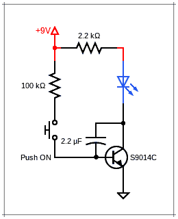
Here’s the list of recommended components to build this simple circuit:
- S9014C NPN Transistor x1
- 5mm Blue LED x1
- 100KΩ ¼ W Resistor x1
- 2KΩ ¼ W Resistor x1
- 2uF/16V Electrolytic Capacitor x1
- 6F22 9V Battery x1
- Push-On Button Switch x1
How does this circuit work? Although this is a simple piece of analog electronics, I’m going to give you a short theoretical explanation!
After switching on the circuit by the momentary button switch, the base voltage of the S9014C transistor is divided between the 2.2uF capacitor and the base of the transistor. As the capacitor charges, the voltage drops across it decreases, and the voltage at the base of the transistor increases.
When the capacitor has reached its maximum voltage, the transistor turns on at maximum, and after that, the capacitor does not permit any further current to pass through, so the base current flows completely into the base of the transistor and switches it on completely.
If the circuitry is switched off, the capacitor supplies the base with voltage. Since the capacitor then discharges, the base voltage also steadily decreases, and as a result, VCE increases.
Note at this point that when you open the momentary button switch, only the low base current causes a change in the capacitor voltage. And that change in collector voltage sabotages the rapid discharge. As follows, while the base voltage falls slightly, the collector voltage rises sharply, and this slows down the change.
You can consider this circuit like an integrator as the output voltage shifts with input current and time. In other words, a larger current (or a longer time) gives a more bombastic change in the output.
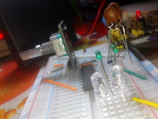
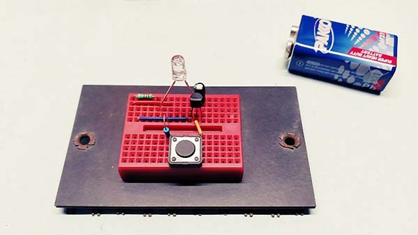
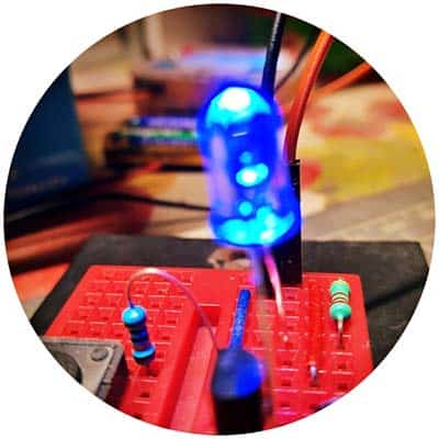
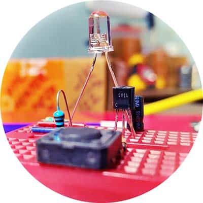
As usual, I rigged up my quick test setup using a mini breadboard and components taken from a junk box. It works just fine!
The forward voltage (VF) of the randomly selected 5mm water clear Blue LED I used here is fairly close to 2.8V (Thanks to my LED Tester/Evaluator).
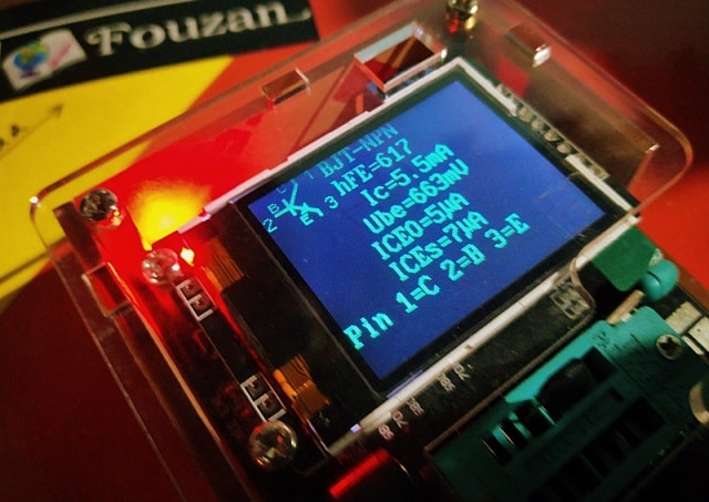
Similarly, the S9014C transistor (https://www.rcscomponents.kiev.ua/datasheets/s9014-datasheet.pdf) used here is taken from my junk box and it has a DC current gain (HFE) close to 600 as indicated by my digital transistor tester.
Below you can see a candid shot of that quick evaluation:
Notice that application ideas are left to the reader’s imagination because there are so many ways to use this little circuit. Another advantage is that none of the components are very critical. That means, you can not only substitute the BJT and LED with other available types, but also finetune the circuit operation by altering the values of the RC components.
Honestly, I happened to find this ludicrously odd design idea in a German blog for electronics projects and the like. Despite some theoretical doubts, I loved trying it out. Needless to say, all agile tests on my workbench were really exciting!
To conclude, now you know how to turn an ordinary light-emitting diode into a glowing dot to make the burning eye of your kid‘s toy respond madly to a gentle touch. And let it live with an unblinking eye gaze at you from out of the darkness!

Quick Talk: LED as Light Sensor!
Finally, after successfully completing the above experiments, I decided that it would be fun to begin another play with those few parts left on the breadboard to fill my free time.
I already knew that in addition to emitting light, an LED can be used as a photodiode, and this capability may be exploited in a variety of applications. So, I ended up with the below blueprint.
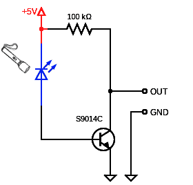
After setting up, use a well-regulated 5VDC power supply to power the circuit, and use your digital multimeter (or oscilloscope) to monitor the voltage at the collector lead of the transistor. To do the test, try exposing the blue LED in the circuit to a strong white light source held at a close distance, and observe the voltage seen at the collector node of the transistor. Got anything amazing?
In another post, I will share a true practical example based on this idea (lots to learn then, and it gives you more pointers). Now, have your say about what you just read. Leave me a comment in the box below!