Sometimes you may want to detect the deflection of the needle of an instrument by a non-contact method. If so, this idea might help you!
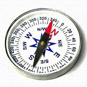
I will now show you a simple technique for optically sensing the motion of the needle of a measuring instrument. Here, that intended device is a magnetic compass.
The magnetic compass is the oldest and most familiar type of instrument for determining direction on the surface of Earth by means of a magnetic pointer/needle that aligns itself with Earth’s magnetic field (https://en.wikipedia.org/wiki/Compass).
Okay, let’s move to the design idea of the simple optical needle/pointer deflection sensor that provides a TTL (transistor-transistor logic) output and, if desired, actuates an external relay. A rough idea of the scheme is depicted below (only a minimal amount of effort is required).
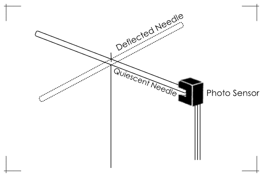
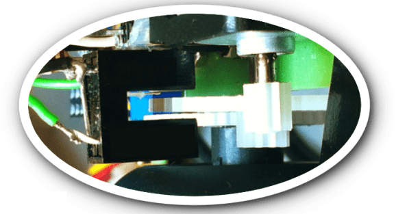
Note: When the needle of the instrument stays in its quiescent state, the photosensor should be positioned so that the tip of the needle fits into the narrow slot of the photosensor. Then ensure that the light beam is interrupted when the needle part is in the slot.
The key component – the optical needle sensor – employed here is a photo interrupter. There’re mainly two types of optical sensors – reflective and transmissive. In a reflective sensor, the light transmitter is positioned next to the light receiver whereas the transmitter is positioned opposite the receiver in a transmissive sensor. In both sensors, the transmitting light is influenced by an object on its way to the receiver.
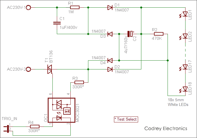
The basic elements of an optical transmissive sensor, also known as a photo interrupter, are a light emitter and a light detector. Typically, an infrared light-emitting diode (IRED) and a phototransistor are used. Below figure shows a typical optical transmissive sensor circuit with a voltage comparator.
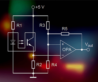
In this circuit, the anode of the light transmitter is connected to the power supply via the resistor R1, and its cathode is grounded. The resistor R1 adjusts the irradiance by limiting the forward current of the light transmitter component (infrared light-emitting diode). The collector of the light receiver component (phototransistor) is connected to the positive power supply rail directly but its emitter is grounded via a resistor R2.
If an object is moving towards the aperture the light will be blocked and the collector current decrease. Likewise, if the object is moving away from the aperture again the collector current increases in the same manner. With this method, an object can be detected without any mechanical or electrical contact. The output signal of the photo-interrupter can be processed by a subsequent circuitry like an analog amplifier, comparator, or Schmitt-Trigger (a comparator is used in this application example).
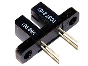
Here’s the datasheet of TCST2103 (VISHAY) transmissive optical sensor with n-p-n phototransistor output https://www.vishay.com/docs/81147/tcst2103.pdf
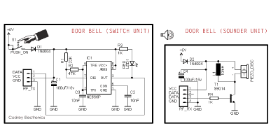
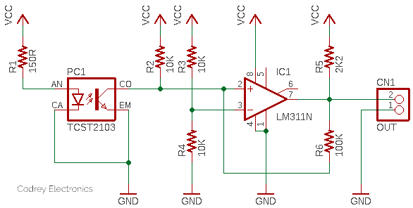
In the below practical circuit, the comparator (IC1) is wired in a way that its output becomes HIGH when the light beam inside the photo-interrupter (PC1) is blocked and goes LOW when the deflection of the instrument’s needle (or meter pointer) moves to allow an uninterrupted light beam. Since the entire circuitry is powered by 5VDC (VCC=5V), its output is TTL compatible!
- LM311 IC Datasheet https://www.st.com/resource/en/datasheet/lm211.pdf
As an aside, measuring the rate of revolution of a motor with circuits like this often becomes a very practical solution because it greatly improves the signal quality.
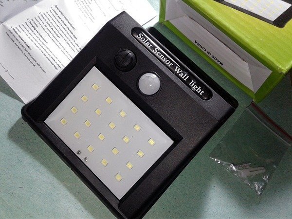
On the other hand, if you’re not ready to gather components to build the above-suggested circuit, you can quickly buy a cheapo photo interrupter sensor module to get on!
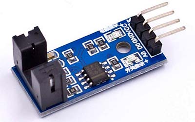
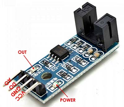
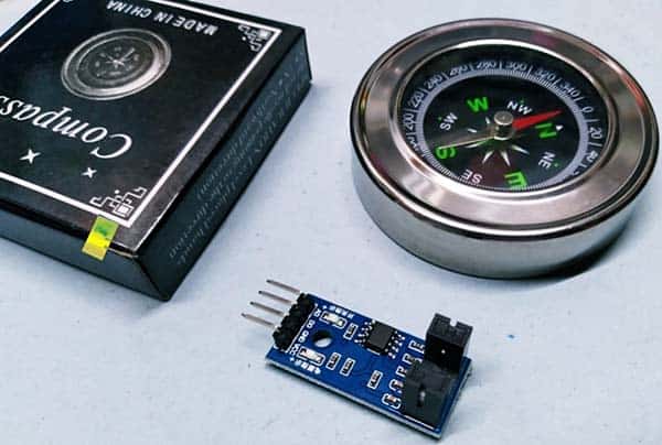
This is the photograph of the quite popular “Groove Sensor” module widely used in motor speed detection projects. This LM393 IC-based module gives a LOW-level TTL output if the infrared light path inside its photo-interrupter is not blocked off by an object.
- Working Voltage: 3.3V to 5V
- Groove Width: 5mm
- IC: LM393 comparator
- VCC: +V
- GND: 0V
- DO: Digital Output (LOW when there’s no beam interruption)
- AO: Analog Output
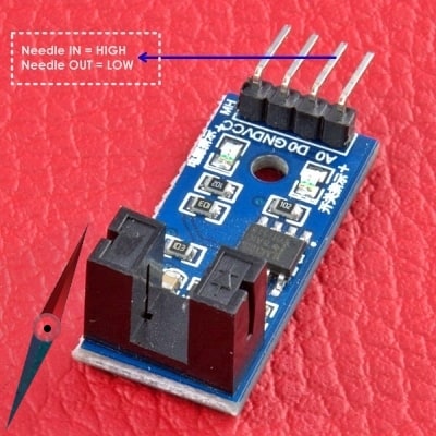
The DO gives a nice digital HIGH/LOW signal that is good enough to be fed to a microcontroller‘s digital I/O pin. Note that the DO pin will render a logic-low signal when the needle in our needle deflection sensor setup turns aside and away from its default position (normally the output stays in a logic-high state).
In closing, now that you’ve taken a closer look at the random build ideas of a simplistic optical needle deflection sensor. Well, it’s the time to pick your magnetic compass, go to its inside, hack its pointer’s mechanism as necessitated, and give this fun activity a try.
Next is the do-it-yourself project of a low-cost compass magnetometer for investigating magnetic disturbances and other magnetic phenomena. The instrument’s construction, including the add-on electronics, is not very difficult. I hope that the upcoming project will bring lots of pleasure that only making things yourself can provide. So, stay tuned!