A timely review is beneficial to all. So, here’s the long-awaited sequel of my old post about infrared motor speed sensors and motor speed sensor modules.
This is the direct link to read that popular post over again https://www.codrey.com/electronic-circuits/rpm-infrared-tach-rough-realities/
Okay, let’s move on to the updated notes…
As clearly pointed in the aforesaid post, measuring the motor speed with the infrared reflective sensor method, while working, turned out not to be a very sensible solution. So, I switched from the reflective sensor method to the transmissive sensor method. And, it greatly improved the signal detection quality.
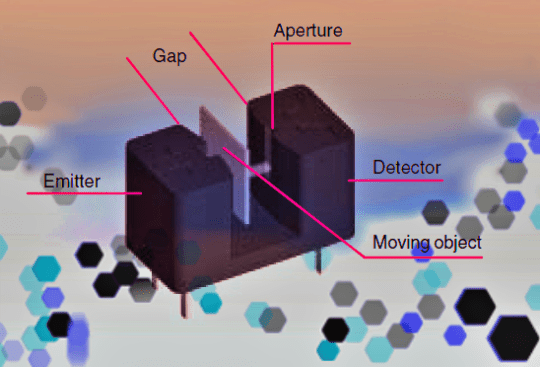
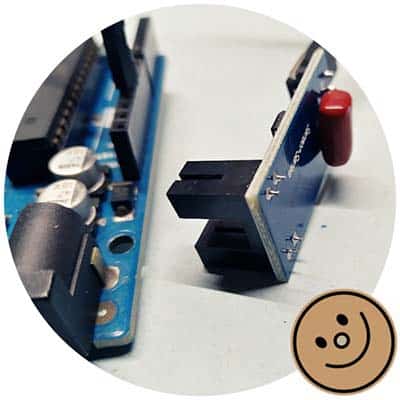
The basic elements of a common optical transmissive sensor used for small distances and narrow objects (also known as photo-interrupter) are an emitter and a photodetector. Here, the emitter/light transmitter is positioned opposite the detector/light receiver. Typically, an IRED (infrared emitting diode) is used as the emitter and a phototransistor is used as the detector.
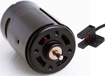
To get started, I chose an inexpensive Chinese Infrared Speed Sensor Module (FC-03), also called the Groove Coupler Module by some vendors. The minuscule module I had on hand allowed me to experiment and make sure things worked before I rigged up my final setup.
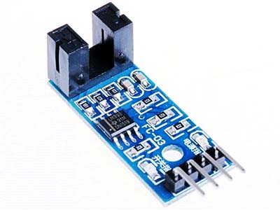
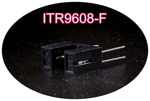
The transmissive sensor used in this module is the ITR9608-F Opto-interrupter consists of an infrared emitting diode and a silicon phototransistor, encased side-by-side on a converging optical axis in a black thermoplastic housing (www.everlight.com).
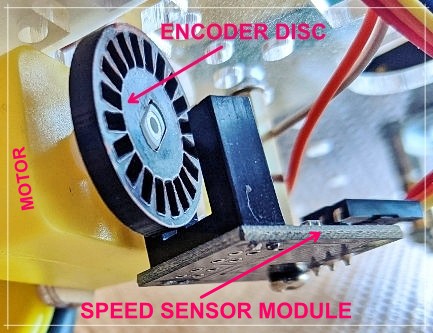
In robotics, a speed sensor module helps determine odometry through a wheel encoder mechanism which usually employs an encoder disc divided up into segments. The encoder disc is then mounted to the rotating part, either on the wheel itself or the motor shaft. So, when the wheel/moto shaft reels, it also reels the encoder disc.
The transmissive sensor coupled with the encoder disc detects the transiting from one segment to another which is informally called a tick. Each tick typifies the amount the wheel has reeled counting on how many segments divide up the entire encoder disc. That means, if there’re 20 total segments in the disc, the speed sensor detected the passing of 20 ticks when the wheel has reeled 1 full rotation.
As in the case of most generic Chinese sensor modules, the speed sensor module demoed here is also designed around the dual differential comparator IC – LM393. A comparator circuit proves quite useful when we want to derive a digital signal from some analog input.
Note that the module gives a HIGH-level TTL output through its D0 output pin if the infrared light path inside the photo-interrupter is blocked off by an object. Otherwise, it provides a LOW-level TTL output.
So, it renders a sensible digital output signal of 5V, that’s good enough to be fed to the digital I/O pin of a 5V microcontroller. Now it should be noted that the comparator circuit in the module has no hysteresis. Therefore, the digital output might become unstable around the switching point and often lead to erroneous results.
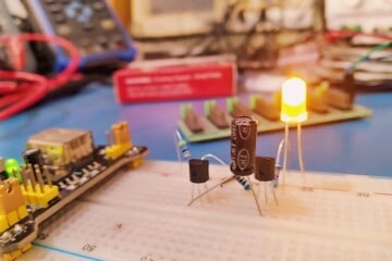
Okay, let’s see a basic test setup in action.
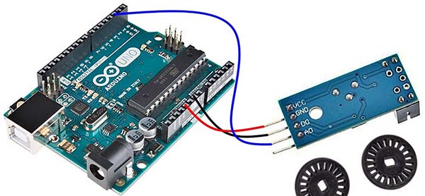
The following figure shows the electrical diagram made for the quick test so that the wheel encoder and Arduino work correctly. Look, my encoder disc has 20 segments (holes).
Below is the Arduino Uno Sketch. Also, note that I borrowed this code snippet from the web and edited it a bit. I know this is not a clever approach to get the job done, but it works. I’ll update this when I get the chance.
int encoder_pin = 2;
unsigned int rpm;
volatile byte pulses;
unsigned long timeold;
unsigned int pulsesperturn = 20;

void counter()
{

  pulses++;
}

void setup()
{
  Serial.begin(9600);
  pinMode(encoder_pin, INPUT);
  attachInterrupt(0, counter, RISING);
  pulses = 0;
  rpm = 0;
  timeold = 0;

}

void loop()
{
  if (millis() - timeold >= 1000) {
    detachInterrupt(0);
    rpm = (60 * 1000 / pulsesperturn ) / (millis() - timeold) * pulses;
    timeold = millis();
    pulses = 0;
    Serial.print("RPM = ");
    Serial.println(rpm, DEC);
    attachInterrupt(0, counter, RISING);
  }
}
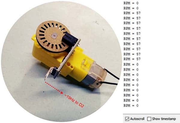
As you can see, we use an Arduino interrupt in RISING mode in this code, which means, the microcontroller only detects all the upward slopes of the received impulses. Moreover, for the module to work correctly with the Arduino UNO, a 100nF capacitor must be added between the module’s digital output signal D0 and GND as shown in the photo below.
In an upcoming post, we will try a different wheel encoder trick to read the wheel velocity information to compute a model vehicle’s odometry. So, stay tuned!
Also, as usual, if you have any suggestions or questions, don’t hesitate to contact through the comments box below. Happy learning and building!