Governing the speed of a motor is very important in many situations especially in mechatronics. By measuring the speed of a motor, we can then adjust the motor’s speed to exactly what we want. Along the same lines, hence it’s necessary to know the exact speed of the motor, in rotations per minute (RPM) for example. As you might know, the term ‘tach’ simply denotes a measuring instrument for indicating speed of rotation.
Luckily we can find numerous versions of cheap infrared (IR) proximity sensor modules and photoelectric encoder modules in the market to carryout the RPM measurement tasks at ease. Following is the photo of such an easy to use IR proximity sensor I found it amongst Chinese infrared tach sensor modules.
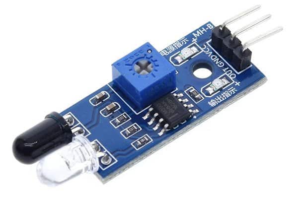
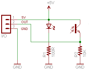
The module, commonly known as “IR speed sensor module”, is built around one LM393 comparator IC. The ‘actual’ speed sensor in the module is a combination of a water-clear infrared LED and a black infrared photo transistor (not an infrared diode). Below you can see its typical schematic, borrowed from a Chinese seller’s website.
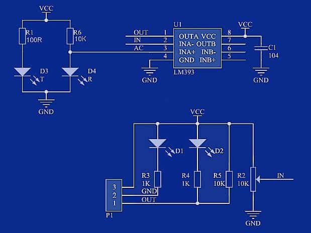
In this particular 5VDC infrared speed sensor module, one LED indicates the presence of input voltage. When there’s a reflective object in front of its ‘eye’, another LED lights up, and the DO output goes to low (L/0V) state. Otherwise, DO output remains in high state (H/5V) because of the onboard 10KΩ pull-up resistor. As usual, the switching threshold can be adjusted with the 10KΩ trimpot.
Is this a really good speed sensor module?
I’m not all that satisfied actually as it’s a bit hard one to put into practice! This session shows you what I’ve experienced in hopes that you might get some helpful hints to proceed well while you’re experimenting with your infrared speed sensor modules.
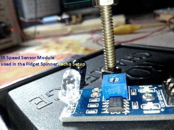
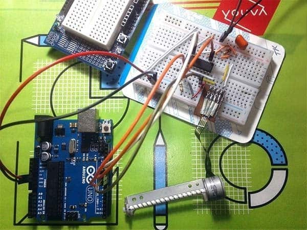
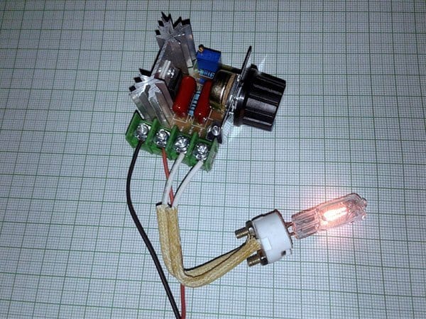
Recently I made a funny ‘fidget spinner accelerator’ out of a couple of parts laying around. In order to determine what’s happened I wanted to have a tachometer that gave reliable results. For the speed test, at first I used my laser tachometer and got reasonable results. However, when I moved to the next self-made tach setup composed of an Arduino Nano and the introduced infrared speed sensor module, I found nothing but fuzzy readouts. It seemed that the tach system indicates higher (and random value) RPM than the fidget spinner’s actual RPM!
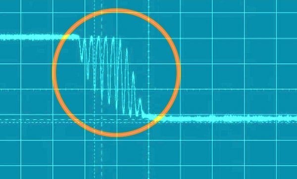
First I thought perhaps the Arduino interrupt code that don’t correspond to the output pulses of the speed sensor module leads to a wrong pulse count and an un-sync to the fidget spinner. Further looking into that, the root cause seems to be the ‘noisy’ output signal from the speed sensor module. It’s observed that the ‘falling edge’ of the square wave signal (outputted by the speed sensor module) has a lot of nasty rebounds (see below).
Since I used a well-regulated, clean, linear DC power supply, there’s nothing to distrust. My Arduino Tacho code (Interrupt on D2/Falling) is a proven one, as well. So I took a look back into the module’s schematic, and its pcb layout, but didn’t caught anything out of the norm.
The LM393 used in the speed sensor module is a dual-independent precision voltage comparator IC with open-collector outputs (ISink = 20mA maximum). Since the output of the module (DO) is already pulled to +5V through one 10KΩ resistor, I just grounded (ac-coupled) the same output through a 100nF capacitor just to learn what’s happening there in the DO output. Surprisingly with the change, I got quite reasonable output signals!
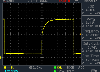
As you can see in the above oscillogram, the signal is a bit distorted during ramp up (see rise time). It’s because of the added 100nF capacitor, but the microcontroller can interpret this signal well. You can try other RC values to tweak this – I also tested my proto with a 1KΩ pull-up resistor and a 10nF bypass capacitor successfully. Perhaps, the 1KΩ pull-up resistor in lieu of the existing 10KΩ resistor won’t allow relatively feeble currents to cause a spike out – who knows.
Do It Yourself or buy?
On the web there’s very little information on erroneous function of these infrared speed sensor modules. What it has taught me is that there’s no easy way to use the module through microcontrollers without some minor tweaks either in hardware or in software. To be frank, the voltage comparator circuitry is superfluous here as a combo of one infrared/laser light sender and one light receiver will do the job perfectly. Further, the comparator has no hysteresis so it’s unstable around the switching point. We can fix the hysteresis problem by adding an appropriate resistor (10K-100K) between pins 1 and 3 of the comparator, but not easy to solder it onboard.
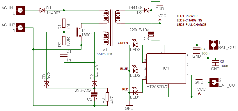
The better solution however is to build a bare ‘speed sensor head’ for your infrared tach yourself. It should be noted that you might need to apply a ‘reflective’ infrared sensing or ‘thru-beam’ infrared sensing method as necessitated. See following schematic tried and tested by me.
When it comes to the software, code/sketch for Arduino in particular, you can use interrupts (rising /falling) – D2 as an interrupt, for instance. That means, use interrupt service routine to sense the tacho signal. Keep note, internally Arduino’s AVR processors use interrupt numbers starting at zero, as opposed to using the pin numbers. For Uno, D2 is interrupt0 (INT0) whereas D3 is interrupt1 (INT1). Further, while calculating the RPM and updating the display, make sure to ‘average’ the readings to help smooth out the final readout.
In this schematic, you can raise the value of the infrared LED’s (D1) current limiting resistor within limits (100Ω to 470Ω). Likewise, value of the phototransistor’s (T1) load resistor (R2) can be lowered if necessary (10KΩ to 4K7Ω).
Comparator and hysteresis
Somebody here still want to buy cheap speed sensor modules rather than trying to build them at home. As mentioned earlier, the worst component in the module is the LM393 IC, and there’s no practical, reliable use for the module. Quite useless!
Anyway, it’s not hard to try the same LM393 IC to build a reliable speed sensor but you’ll need to cure the aforesaid hysteresis issues. See page 14 of the LM393 official datasheet to get some useful ideas http://www.ti.com/lit/ds/symlink/lm393-n.pdf
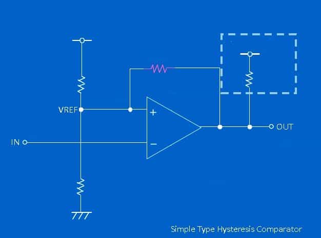
Comparator ICs are designed to compare the voltages that appear at their inputs and to output a voltage representing the sign of the net difference between them. Hysteresis can be added to a comparator circuit to improve its stability, especially when the input signal is noisy. Hysteresis is applied by feeding a small fraction of the output voltage (which is at an upper or a lower limit) back to the positive input. This voltage adds a polarity-sensitive offset to the input, increasing the threshold range. Note that a comparator cannot be operated as a hysteresis comparator when a negative feedback is applied.
In a single supply, non-inverting hysteresis comparator, its resistor divider creates a positive reference voltage that is compared with the input. The equations for designing the dc thresholds are included in the below figure (Ref: Analog Dialogue 34-7/2000).
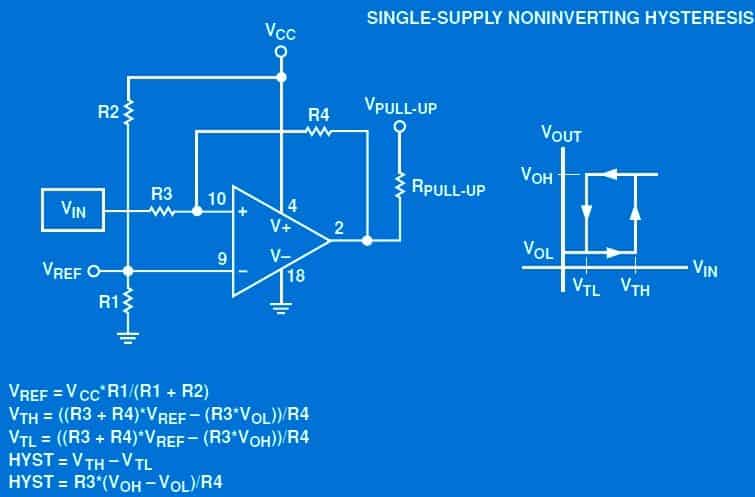
Briefly, you can use hysteresis to rid comparator circuits of instabilities due to noise. Hysteresis is reliable and can be applied predictably using small amounts of positive feedback.
Time for a little update
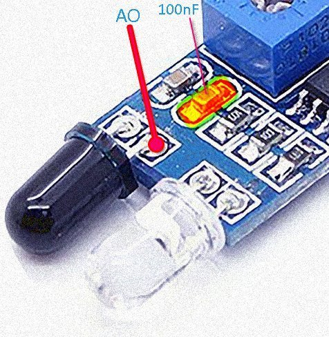
In this update, I took another idea. Although the 3-pin speed sensor module doesn’t provide an analog output (AO), we can tap it easily as shown in the next picture. A good note is that there’s a100nF capacitor soldered across the phototransistor, so you can try the analog output without the inclusion of an external capacitor. Just feed the microcontroller the analog output (AO)!
Future plan: Create a compact digital tachometer using a better speed sensor head to provide incessant speed indication in every situation. Estimated cost of the do it yourself project is under $15. Sure beats having to buy pricy commercial tachometers. So, stay tuned!
Thanks for the writeup.
I have the 4 pin version with AO and DO.
It looks like hysteresis can be added by adding a large resistor between the outputs (i.e. extenrally…), as the AO seems to be the +ve input on the comparator…
Simon: Yes, it is possible. That concept is covered in the “comparator and hysteresis” section of this post. Thanks!