Lithium-ion Battery & Lithium-ion Battery Charger
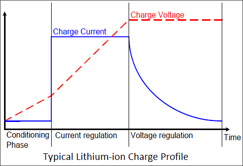
Lithium-ion (Li-ion) batteries have become popular for portable electronics such as smart phones because they boast the highest energy density of any commercial battery technology. Since Lithium is a highly reactive material (incorrect charging of a modern Li-ion cell can cause permanent damage, or worse, instability and potential danger), Li-ion batteries need to be charged following a carefully controlled constant current/constant voltage regime that is unique to this cell chemistry.
Lithium-ion Universal Battery Charger
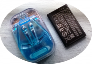
The charger framed here is a $1 Chinese product available under different brand names. With the help of an adjustable contact set, this charger is able to charge nearly all common Li-ion rechargeable battery packs. Following is an explaination on how to power the charger, load a battery into the charger, and charge it.
- Plug the charger in AC wall outlet (AC180 – 240V)
- Place the battery pack on the base (3.7V Li-ion)
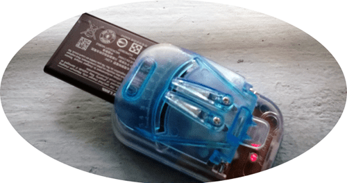
- Move the charger contacts to align with the “+” and “–” terminals of the battery. The charger will automatically detect “+” and “–” polarity
- Now the “power” indicator lights up & “charging” indicator will flash during charging
- “Full Charge” indicator lit up when battery is fully charged
An important feature of this charger is the built-in reverse polarity detection mechanism. When we insert a battery, the system automatically adjusts its output polarity as per current situation to ensure a safe and healthy charge process. Further, the smart adaptive charging algorithm offers cheerful features like end-of-charge detection, top-off charge, over-charge protection, dead-battery detection, near-dead battery rejuvenation, etc.
Teardown Reflections
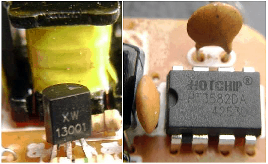
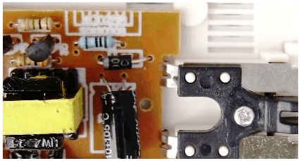
- Inside electronics: Electronics of the charger comprises of two equally-important sections; an “odd” smps power supply, and a “mysterious” battery charger. A major component in the smps circuit is one TO-92 transistor 13001, while the battery charger is built around one 8-pin DIP chip HT3582DA from HotChip (http://www.hotchip.com.cn). According to the datasheet, HT3582DA is a universal battery charger control chip with automatic battery polarity identification, short circuit protection, and over-temperature protection (max current 300mA).
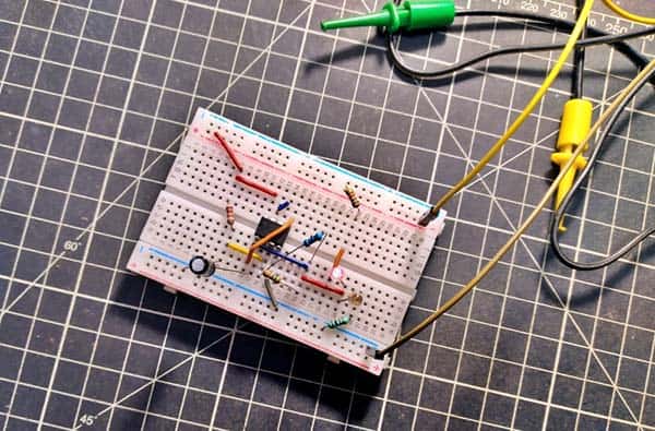
Here is its inside:
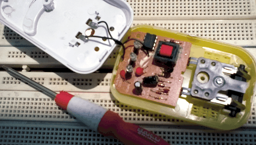
I also noticed that the circuit board itself is very generic – the main thing that separates one charger from many others on the market is the alteration in the SMPS circuit (more on later-see lab note).
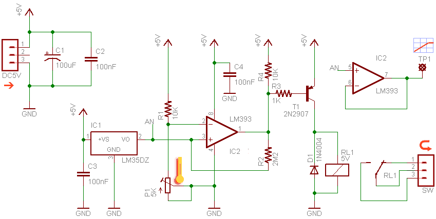
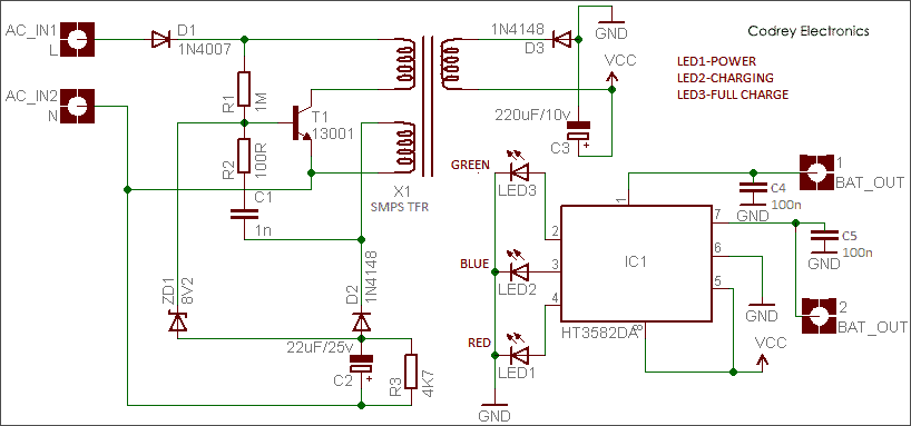
- Circuit Diagram: Now is a good time to move to the schematic of the grubby looking circuit board (traced & verified by me).
- Lab Note: As indicated before, the main thing that separates one charger from many others on the market is the alteration in the SMPS circuit. As an example, it was observed that the value of R1 modified to 1.5M or 2.2M, and R2 to 56R or 47R in some other chargers. Similarly, C2 was replaced by a type 10μF/25v.
Unfortunately, nothing more available about the smps transformer (X1), and the charger controller chip (IC1), except a Chinese datasheet filled with some raw data. Next wonder is the absence of a traditional high-voltage dc filter/buffer capacitor (usually one 4.7μF – 10μF/400v type) at the front-end of the smps. However, it’s clear that the high-voltage 1N4007 (D1) input diode converts the AC input to pulsating DC. The 13003 power transistor (T1) switches the power to the smps transformer (X1) at a variable frequency (probably higher than 50kHz).
The smps transformer has two primary windings (the main winding and a feedback winding), and a secondary winding. A simple feedback circuit regulates the output voltage; the feedback oscillation from the feedback winding and the voltage feedback from the associated components are combined in the 13001 power transistor. The transistor then drives the smps transformer. On the secondary (output) side, the 1N4148 diode (D3) rectifies the smps transformer output to DC, which is filtered by the 220μF capacitor (C3) before providing the desired output voltage (near 5V) to the rest of the circuit.
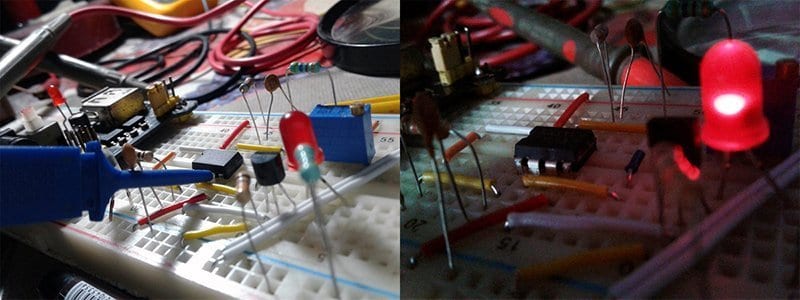
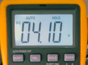
Throughout the time of the teardown experiment, 4.1 V DC was found across the charger contacts (without battery), and the presence of a pulse activity was also observed there (with battery).
And finally, it’s assumed that PWM output (at a certain frequency) generated by the battery charge controller chip HT3582DA charges the battery. The in-built ADC and PWM (with zero external components) provides a means to implement an efficient lithium-ion battery charger!