Here is the circuit of a do it yourself universal relay module for microcontroller projects. One advantage of this design is that it can work with both active-high and active-low TTL signals from the I/O of any microcontroller. The circuit is infact a powerful electromagnetic relay with rich galvanic isolation, rated for 240VAC operation. This is the type of relay you will need to switch mains powered devices. The relay will handle almost all devices used in homes, however, ensure that the power rating (VA) of the device to be connected with it is less than the actual power rating of the electromagnetic relay.
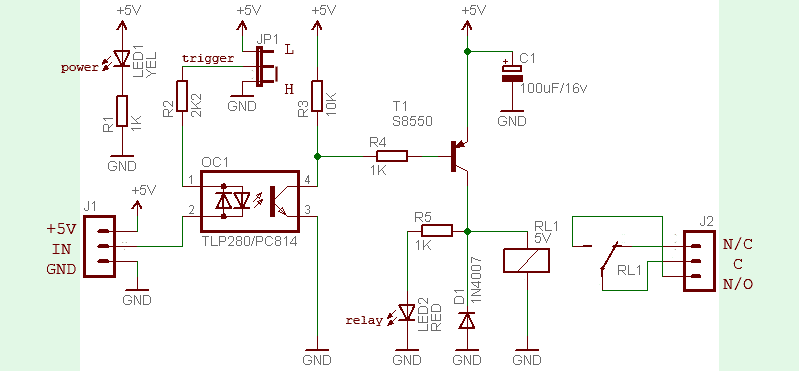
As can seen from the above schematic, the design is centered around an ‘ac’ opto-coupler (OC1). Remember, an ordinary opto-coupler will not work with this concept. The 2-way jumper header (JP1) is for switching active-high (H) and active-low (L) input mode. As you might noticed, I/Os of most microcontrollers can only supply +5V (or +3.3V) and less than 40mA (20mA typical). So, you cannot drive a power relay’s coil directly from that output since 5V power relays usually require more than 50mA to energize the relay coil. This calls for a separate power supply (+5V) to the module in addition to the signal (IN) from microcontroller’s I/O which is used to drive the relay.
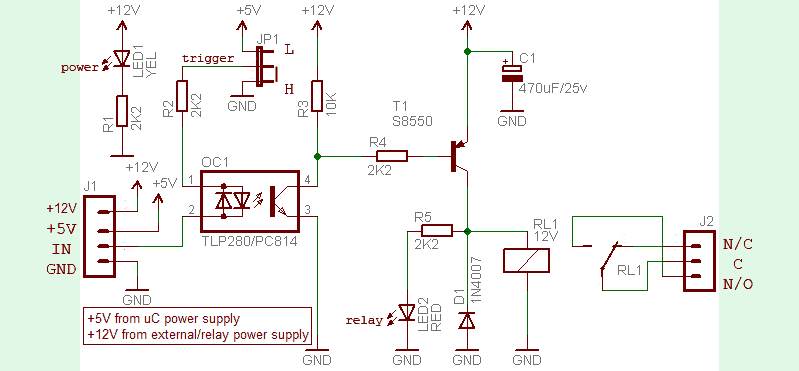
In the schematic, both the I/O drive voltage and the relay coil voltage are the same +5V, and hence there is no problem with active-low input because the voltage being pulled down by the I/O will not be more the 5V (actually the galvanic isolation is not very important here). But this is not the case for a 12V relay. If you want to to use a 12V relay driven by a 5V I/O, and you’re using an active-high I/O, there’s nothing wrong. But problems can occur if the relay is driven by an active-low signal because this may damage the concerned I/O or the whole microcontroller.
Shown below is the schematic revised for 12V relay operation. As you can see with the opto-coupler and a separate Vcc input (+5V from the microcontroller’s power supply), the I/O is perfectly isolated from the +12V relay voltage. This idea prevents the 12V being feedback to your microcontroller’s 5V I/O, when driven by the active-low signal.
Pre-wired relay modules are very convenient for interfacing power relays for switching application in your projects. This module can be configured in two modes using the jumper headers. By default, the relay is controlled by an active-high signal. It also includes two visual indicators so you can see the power input and relay output status. A final point, most power relays commonly use silver alloy switching contacts hence are not suitable for switching very low currents (few milliamperes).This is because the power relays need a ‘wetting current’ to break through the surface film resistance and will not pass very small currents reliably!

Do you have any more modern recommendations for optocouplers? The PC814 is obsolete, as is the TLP. Thanks!
Unless you need something special, EL817 (from Everlight) or any other Chinese knockoff of Sharp’s PC817 would be just fine. I believe that if you don’t have specific key requirements it doesn’t matter so much which you choose.
BTW, for further reference, I would suggest to have a look at http://www.vishay.com/optocouplers/opt-tran-output/
Thanks!
Instead of adding a new input in the second diagram why not increase R2 value?
Lucas: The second diagram is meant for 12V ‘load’ operation, i.e. to control a 12V relay by a 5V signal from the 5V microcontroller. As clearly mentioned, with the opto-coupler and the default Vcc input (+5V from the microcontroller’s own power supply), the I/O of the microcontroller will perfectly be isolated from the external VCC (+12V relay voltage). This trick prevents the 12V being feedback to the microcontroller’s 5V I/O, when driven by the active-low signal. Hope this helps!
Hello, i’m a newbie, so maybe my quetion is stupid, but:
Why LED2 (“relay” LED) should even lights? It’s branch (wich includes 2.2k R5 resistance) is in parallel with the coil of neglible reistance. Shouldn’t that mean that all current from the emitter flows into the coil, but not into branch with LED2?
Thanks for your question Kyrylo!
First try to build the circuit and measure the voltage across the relay coil when it’s active. You will find the answer yourself.
Nonetheless, if you still have any questions concerning a BJT-based relay drive circuit, kindly reach out to me. I will publish an in-depth article on relay driver circuits later.
Thank you for reply
I built the circuit (without optocoupler) and it works – LED2 lights!
As I understood, it is because resistance of the coil is not neglible and it’s resistance is enough to allow some current to flow into parallel branch with LED2.
I got V(Coil) = 7.3 V, I(Coil) = 93 mA => R(Coil) = 78.5 Ohm
Also I found 5V relay datasheet and R(Coil) according to specification is 69 Ohm – pretty close to my reults.
It will be great to reed your next depth article on relay driver circuits.
Would you explain in your next article purpose of the C1 capacitor?
Am I correct, it is used to slow down current drop after power-off to reduce self-induced voltage of the coil?
Also it will be great if in your next article you’ll in-depth explain how diode protects circuit (as i undertand it is also to protect from self-induced voltage?) and transistor biasing.