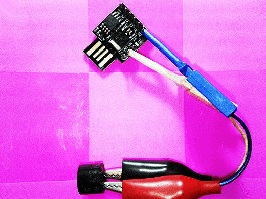
So I have this Tiny Chirp, when you power it up, an indicator wakes up and it does a sequence of wonderful chirps!
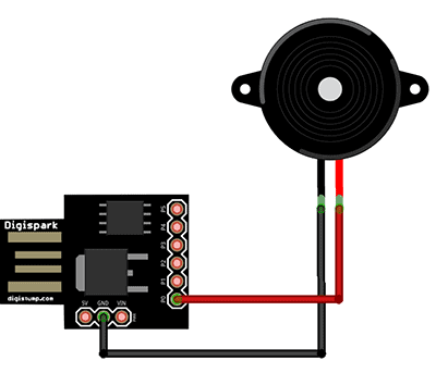
First, you need one active piezo-buzzer (i.e. the type with a built-in sound generator). Next (and last) thing in the list is a Digispark (Rev 3) development board. Enough to meet the purpose!
It’s time to go for the code. Since there’s already a beautiful piece of suitable code by Alex Wulff (www.AlexWulff.com), we can adapt it and put to the test without a cosmetic surgery. As was common, upload the code coming after to Digispark through your Arduino IDE (refer similar articles published elsewhere here), hook up the piezo-buzzer between P0 (+) and GND headers of Digispark board, and do listen to the chirps of the little USB-powered device!
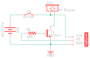
Have need of much higher output just to pierce your neighbor’s ear? Then try 9V battery edition of the same hardware but based on a transistor-based piezo-buzzer driver (see next diagram).
/*
 * Tiny Chirp v1.0
 * Digispark Chirp Maker
 * Tiny sounder for toys, alarm clocks, model bugs, etc.
 * An inspired project (Thanks to Alex Wulff – See Acknowledgement)
 * Authored by: T.K.Hareendran / 2018
 * Published by: Codrey Electronics
 * Site: https://www.codrey.com
 */

#define BUZ      0 // Piezo-Buzzer Pin (PB0)
#define IND       1 // Onboard Indicator LED Pin (PB1)
#define INIT   5000 // Initial Value (ms) to set Total Succession Time

void setup() {

  pinMode(BUZ, OUTPUT); // Buzzer Pin as O/P
  pinMode(IND, OUTPUT); // LED Pin as O/P

  for (int i = 0; i < 5; i++) {  //Self-assurance Indication
    digitalWrite(IND, HIGH);
    delay(100);
    digitalWrite(IND, LOW);
    delay(100);
  }
}

void loop() {  // Making Chirps
  for (int i = 1; i < 50; i++) {
    digitalWrite(BUZ, HIGH);
    digitalWrite(IND, HIGH);
    delay(30);
    digitalWrite(BUZ, LOW);
    digitalWrite(IND, LOW);
    delay(INIT / i);
  }
}

// End Of Code
In the code, onboard LED of Digispark (connected to PB1) is configured as the visual indicator while PB0 (pin 1 of the 6-pin header) is used to drive the piezo-buzzer. The ‘initial’ value of 5000(ms) will yield a total sequence time of roughly 24 seconds. Also note that during initial power up Digispark introduces a one-time delay of few seconds.
Get Your Arduino Chirp!
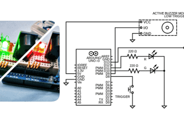
Let me introduce the “Chirp” library that enables your Arduino Uno to output chirp audio via attached audio hardware. You’ll need an Arduino Uno (or Mega2560), and of course the Chirp library (https://github.com/chirp/chirp-arduino). Once Chirp is installed as a library, copy-paste the following code in the Arduino IDE, and upload it to your Arduino Uno. Here, a chirp object is created and is used to chirp the ‘parrot’ over and over, with two-second gaps ( this is just to assure your library is installed and functioning).
//Parrot Chirp
// D3 is the Audio O/P pin

#include <Chirp.h> // Required Library

Chirp chirp;

void setup() {} // Nothing To Do

void loop() {
    chirp.chirp("parrotbilllllahcm4"); // Chirp Identifier
    delay(2000);
}
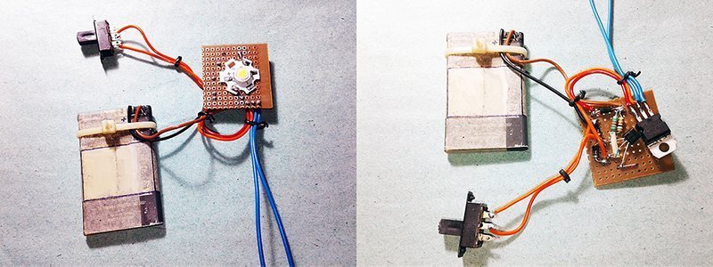
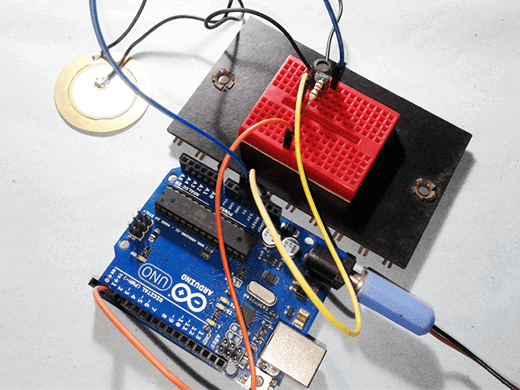
Although you can connect a standard piezo-disc (not a piezo-buzzer) directly to the Arduino pins (D3 and GND), I have had success driving the piezo-disc with the simple audio hardware shown below.
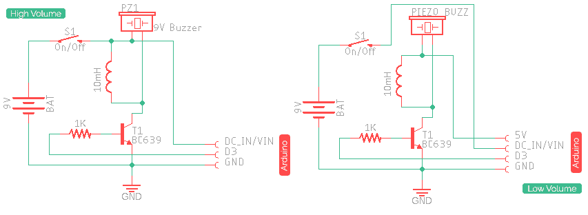
This audio hardware is designed quickly (certainly not a perfect solution) to run on 9V battery supply. In the first version (left), the piezo-disc also runs on the same 9V and hence gives a comparatively louder sound output. In the second one (right), the piezo-disc is powered by the 5V dc supply from Arduino board, hence yields much lower sound output (do it yourself as desired).Value of the coil connected across the piezo-disc does not matter too much, a value in the range of 10mH to 50mH seems to give the best results with most piezo transducers. Also, the transistor part number is not very critical but it should be a high collector-emitter voltage (VCEO :: BVCEO) type because the piezo-disc may be driven up to 40-80V.
However, note that the signal supplied (on D3 of Uno) is a 62.5kHz (5V), PWM approximation to an ideal audio waveform, so it’s up to your attached audio hardware to smooth this signal. Ideally, the smoothing would be carried out by extra filter circuitry before the output is fed to the audio hardware, however in practice the 62.5kHz pulse train is at too high a frequency for audio hardware to pass unchanged, hence a simple speaker will naturally smooth the signal. The PWM technique is explained further in the library maker’s GitHub.
Now it’s your turn. Get ready to start playing with your own chirp code, and your own audio amplification/smoothing hardware, etc. Once again, remember that the exact nature of the smoothing (and so the fine characteristics of the sound output) will depend largely on the particular audio hardware that you attach. Happy Chirping!!!