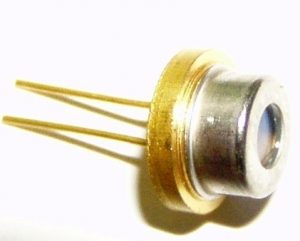
Recently I got a couple of powerful laser diodes from a friend abroad. The ‘invisible’ (infrared) laser diodes with 1000mW and 2000mW power (808nm wavelength) are good for numerous applications like solid-state laser excitation, infrared illumination, etc. Technically, typical operating voltage (Vop) of the 1W laser diode is 2.0V and operating current (Iop) is 1.1A, as found in the Xerox of the datasheet that came with the packet.
First Drive
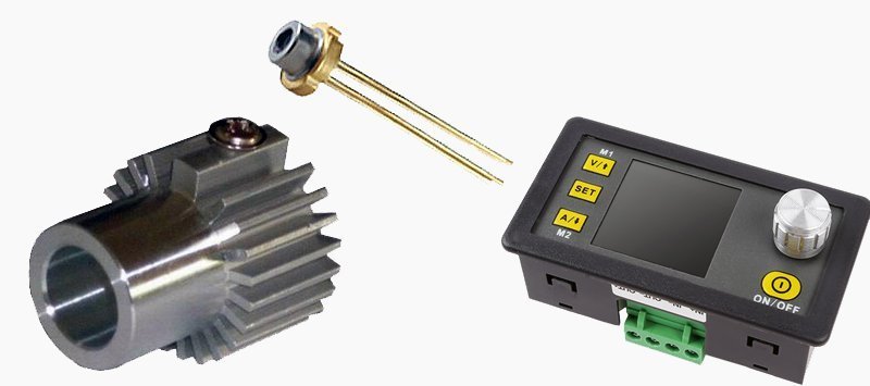
Since there’s no specific design idea in mind, at first I tried powering the 2-pin laser diode (attached to a TO-5, 9mm heatsink) from a digital power supply module and found that the laser diode in close proximity (without any optics) can moderately burn thinnest black plastic films.
Although the laser diode can be powered from an adjustable power supply with a series-resistor, my test method proved to be deficient because it damaged the connected laser diode after a few experiments. Later, I discovered that it’s due to the high-current flow from the buffer capacitor at the output of the power supply module (when power supply was turned on without the laser diode at its output, buffer capacitor got charged to near supply voltage level, and when laser diode was connected to the live power supply, buffer capacitor immediately discharged through the laser diode and resultant current flow destroyed the laser diode bit by bit).
Next Driver
When it comes to an improved laser diode driver, the ubiquitous LM317-based circuitry in current limit configuration would seem a better choice. The LM317 can cater current up to 1500mA which makes it possible to use it for >1000mW laser diodes. We can even add a simplistic PWM (or on/off) control to the driver by interfacing a microcontroller’s I/O through an appropriate circuitry connected with LM317. However, note that this LM317-based idea works well only with infrared (IR) laser diode (not with other higher-voltage colors).
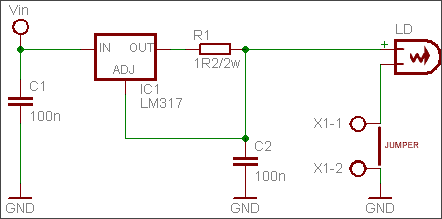
In the above shown schematic, LM317 (IC1) is configured as a constant current source capable of catering 1000mA of output current. Here the 1.2 ohm/2w resistor (R1) sets the output current (I=1.25/R1). Remember, since IC1 has an inherent dropout voltage of ~ 1.5V to 2.5V (depending on the current being supplied and the temperature), you should use a supply voltage (Vin) higher than the target output voltage, ie. the Vop of the laser diode (LD). Besides, you can vary the current being delivered (drawn by the laser diode) by replacing R1with a multi-turn preset potentiometer. Also, try to replace the 100nF capacitor (C1) connected in parallel across the input with a 47-100uF one to ensure the improved stability of the driver.
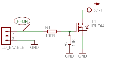
Another advantage of this design is that the jumper (X1) can be replaced with a little logic-level MOSFET based add-on circuit (see next schematic) to use TTL output from any microcontroller for enabling/disabling (H=Enable) the laser diode.
Quick Drive Solution
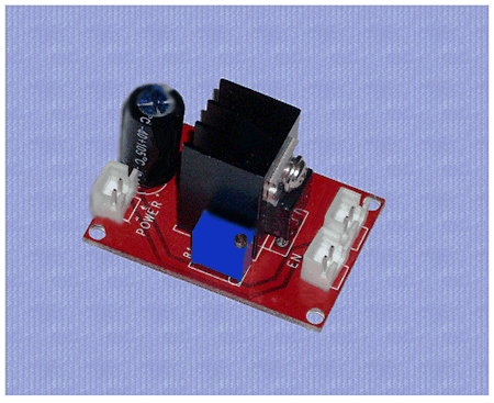
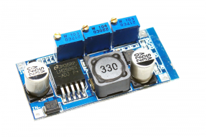
If addicted to eBay, you can find quick solutions for driving laser diodes by fetching one of the CV/CC dc-dc buck converter modules like the one shown below. It’s a low-cost high-power, 1.5V to 33V/3A switching dc-dc buck converter with Constant Voltage (CV) and Constant Current (CC) output capability. At the heart of the module is the venerable LM2596 (https://www.onsemi.com/pub/Collateral/LM2596-D.PDF).
Warning! Laser diode emits extremely dangerous visible and invisible laser radiations, and can cause burns or fire. Never look into a working laser diode (or point it on a reflective surface) as it may permanently damage your eyes!

Shouldn’t you have a resistor in parallel with C2? When T1 is turned off, C2 builds up a charge up to OUT and when T1 is turned on there’d be surge of current through the LD, potentially burning it…
The resistor would be able to discharge C2, preventing burnouts 😉
@Pedro Doria Meunier: Thanks for sharing your insights!
To be honest this article is the part of a bigger project, and hence the circuits should be regarded as experimental. Regarding the issue with surge/spike, it’s already covered in the 3rd paragraph of this article.
I admit, the LM317 will do very little to protect the connected laser diode from transients with, and many laser diodes respond very quickly to transients. To follow good engineering practices, you can of course add a suitable resistor (100K for instance) across the LD. BTW I just retested the design, but didn’t see anything out of the ordinary!