Interest has been growing in design ideas for controlling the speed of heatsink cooling fans in electronic equipments. This article will describe how to simply design and build a governable heatsink/chip cooling fan for your next low-budget project, and will propose some random approaches for you – the designer!
It was off to a good start…
I bought a couple of laptop/notebook processor cooling fans from Flipkart a few months ago mostly out of a desire to support a school science fair project. It wasn’t until last weekend that I thought of something more useful to do with it. Instead of that I started the project of a general-purpose automatic heatsink/chip cooling fan. The project is a really watered-down version of a major-level electronics project that I will be developing farther when I have time. Anyway, I’m not going to leave you with anything though – the little project in the title is reasonably complete. The project is fairly specific to my hardware, but it can at least serve as an example of how to do funny things with cheapo laptop/notebook cooling fans. Well, let’s get started.
Why a laptop/notebook processor cooling fan?
Frankly, you can buy miniature cooling fans and blowers for cheap from almost all online storefronts. The price of a laptop/notebook fan might be relatively high, but such a device has its own advantages. The basic cooling fan/blower is usually a 12VDC type with just 2 wires for power supply connection. So you’ll definitely need an extra power supply & a speed regulator circuit if it’s intended for a 5V microcontroller-based project. On the other hand, a standard laptop/notebook cooling fan usually has 4 wires – apart from the power supply leads it offers a tacho signal (speed information) output wire, and a pulse width modulation (speed control) input wire. Further, it’s normally rated for 5VDC operation and has enough inbuilt electronics to reduce the count of external supportive components.
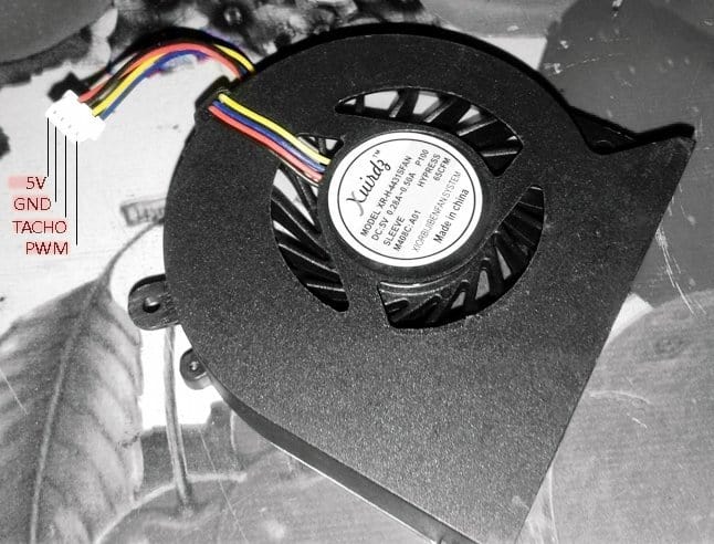
To check a laptop/notebook cooling fan, just connect its positive (5V) and negative (GND) leads to a 5VDC power supply. The fan should start spinning at 100% speed, there’s no PWM control input, though. And, if you link its PWM control input lead to the GND lead directly, you can see that the fan will stop immediately – that’s usual. Sadly, there’s no universal color code for laptop/notebook processor cooling fans, so you should spend sometime on internet to find out its wire color code/connection details. Beware, incorrect/improper wiring/handling will kill your cooling fan in a flash!
As stated before, in addition to the power, ground, and tach signal, 4-wire laptop/notebook cooling fans have a PWM control input, which is used to regulate the speed of the fan, instead of switching the power to the entire fan on and off. An advantage of this method is that the fan speed can be controlled at speeds as low as 10% of the fan’s full speed.
How to regulate the cooling fan speed?
As you might noticed, if no PWM signal is present, the fan will run at on 100% speed, meaning, if you want to run the fan at full speed, simply leave its PWM control input lead free (a crude method) or apply a PWM signal with 100% duty cycle (an advanced method). If you’ve followed my recently posted articles on PWM, you know what I’m talking about. Nevertheless, recall that the typical PWM frequency for cooling fan speed regulation is a rather high frequency (>20 kHz),selected deliberately to move the fan noise outside of the audible range.
Let me start this session with the simplest method of laptop/notebook cooling fan control – the thermostatic, or on/off control as this method is very easy to implement. The fan is switched on only when cooling is needed, and it is switched off for the remainder of the time. The user needs to set the statuses under which cooling is required (typically when the temperature level exceeds a preset threshold).
Before jumped into the game, I took some measurements and found that the particular fan draws about 300mA of current at 5VDC. The open-terminal voltage observed at the PWM control input lead (blue) is about 4.6V while it’s close to 0.9V at the tacho signal output lead (yellow). The tacho signal is roughly 150Hz and duty cycle is 50% when checked with my digital frequency counter.
A typical circuit for a thermostatic on/off fan control usually comprises a comparator circuitry that changes its output signal state when the temperature exceeds a programmable threshold and automatically switches back when the temperature drops a preset amount below the set point. The comparator output signal is then used to switch the fan’s power supply on/off through a suitable driver component, perhaps a BJT or FET. The programmable hysteresis of the circuitry always ensures that the fan does not continually switch on/off when the temperature level is close to the threshold.
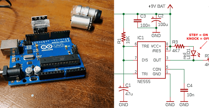
Anyway, my idea is somewhat different (and doesn’t make much sense) as I like using the PWM control input for thermostatic on/off control rather than switching the fan power supply on/off. See the scheme below:
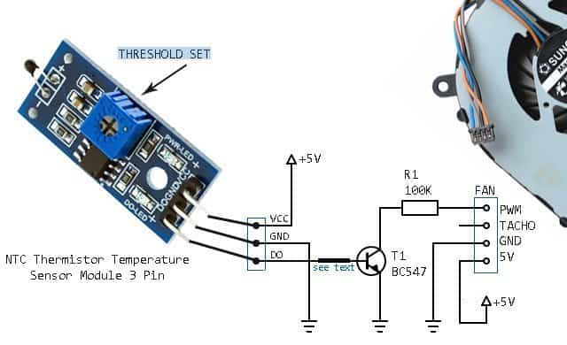
This is a simple circuit wired around a readymade “NTC temperature sensor module” based on the LM393 comparator chip. The ‘active-low’ output of the comparator chip available through DO pin of the module is exploited to switch the fan on/off, ofcourse through the BC547 (T1) transistor, and the 100K resistor (R1).
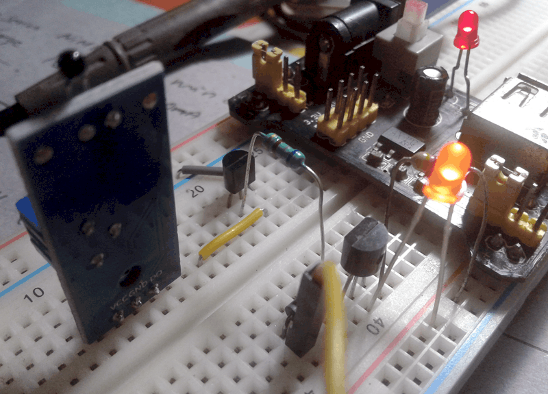
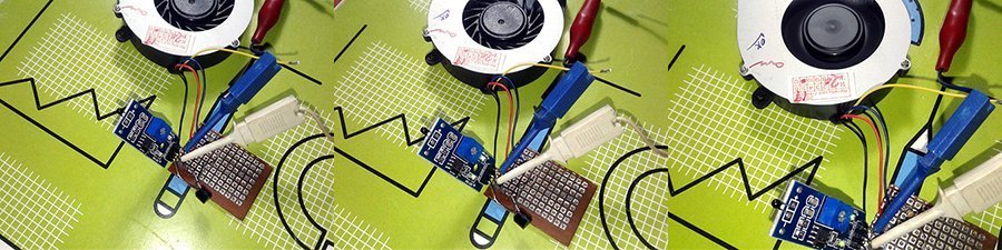
The set point can be varied through the onboard blue trimpot. Note that the DO LED, in this particular setup, lights up always but it’s not abnormal. Finally, you can add a 1K resistor between the DO pin of the module and the base terminal of the transistor, not very essential though. Following is a couple of quick test snaps from my workbench. Really a crude setup, eh?
The above-introduced idea is in fact a fun academic exercise in the unorthodox way to control a laptop/notebook cooling fan. Also, I’m afraid, without being much familiar with the specific electronics inside, there’s no way of knowing exactly how it will respond in the long run. So now I’m moving to the most prevalent method currently used for controlling the speed of a cooling fan – the high-frequency PWM. Here in this method, the PWM signal drives the fan directly i.e. the driver component (usually one FET) is already integrated inside the cooling fan. Reducing the external component count, this approach obviously makes the external circuitry much simpler.
This is the schematic of the manual PWM speed controller for laptop/notebook cooling fan:
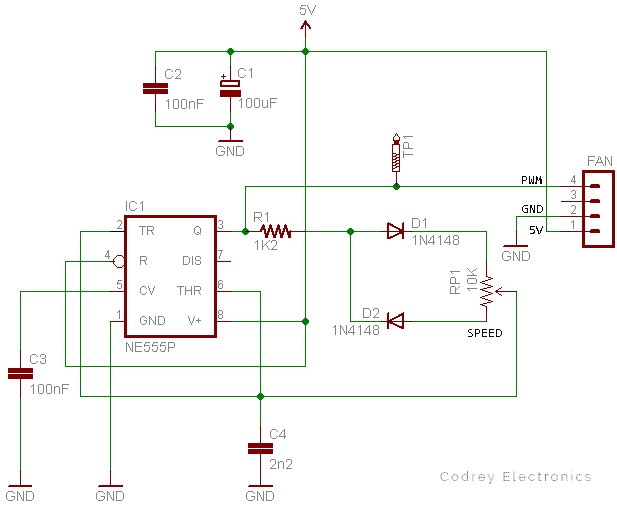
This PWM controller is cheap and easy to build, but has no temperature sensor and automatic control and with components are shown runs at around 20kHz-30kHz frequency. This 555 timer (IC1) based PWM controller offers 30% to 90% pulse width regulation using the standard 10K potentiometer (RP1), while keeping the oscillator frequency relatively stable.
Although output pin 3 of IC1 is used to drive the PWM cycle, the discharge pin 7 can also used as the drive pin. Note that pin 7 is an open-collector output, and hence it’s an active low signal. If you want to be really automatic thermostatic speed control, then you can use an appropriate thermistor between the wiper and one end of RP1 to make the PWM cycle temperature-dependent. Another simple way is to feed variable voltage from an external temperature sensor circuit to the control input (pin 5) of IC1 to overtop the PWM. You can find similar design ideas elsewhere in this website.
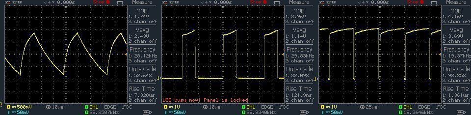
This circuit is optimized for the specific cooling fan in my hand, and ofcourse to work well with the application I had in mind. Anyway, you’re free to modify it by changing the RC components (RP1-C4-R1) as desired. Below you can see random oscillograms captured while probed to Pin2 (left), and TP1 (middle – minimum speed & right – maximum speed).
What’s Next?
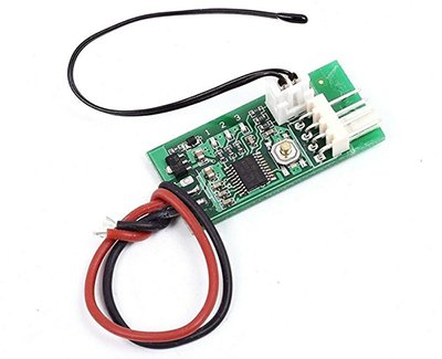
Hope now you learned a few things about using a low-profile laptop/notebook cooling fan as a controllable heatsink/chip cooling fan. I just got inspired by the design of a readymade module (see below), and now working on the build of such a “Universal PWM 4-Wire Fan Temperature Controlled Speed Governor” module. Since I would like to publish the design here (after a bit of playing and experimenting), please stay tuned. Thanks for following along. Feedback is more than welcome!