There seems to be a lot of confusion among electronics hobbyists about how a rotary encoder (knob) works and how to use it with electronics projects. Today, we’ll be examining a very cheap and easily available mini rotary encoder module in more detail, and I’ll guide you quickly through the process of deciphering its output signals.
The mini rotary encoder module
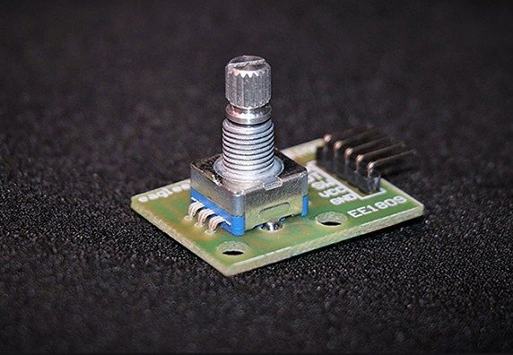
Let me start this article by introducing the cheap mini rotary encoder module usually available from almost all online vendors under different brand names. The pretty cool module is in fact a combination of a simple rotary encoder switch and its support components (just two resistors) wired on a bit of printed circuit board with breadboard-friendly male headers.
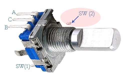
The key component in the module i.e. the simple rotary encoder switch has just 3 pins, and one of those is wired to ground. The other two pins change state and are always either high or low, so they can only have a 2 bit gray code (00, 01, 10, and 11). The extra 2 pins of the encoder are just a simple momentary on/off switch that is activated when you push down the shaft/knob.
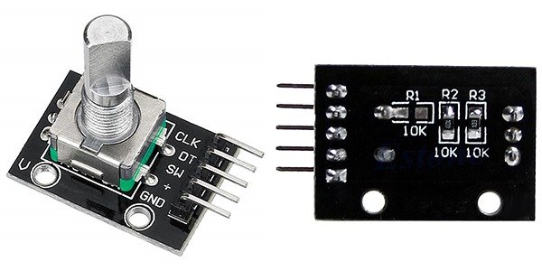
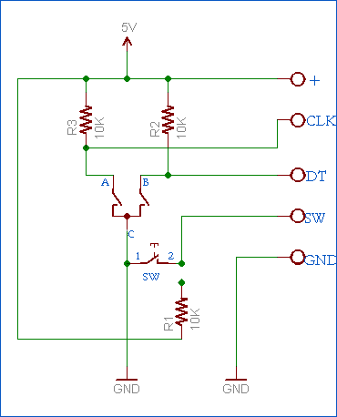
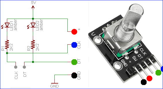
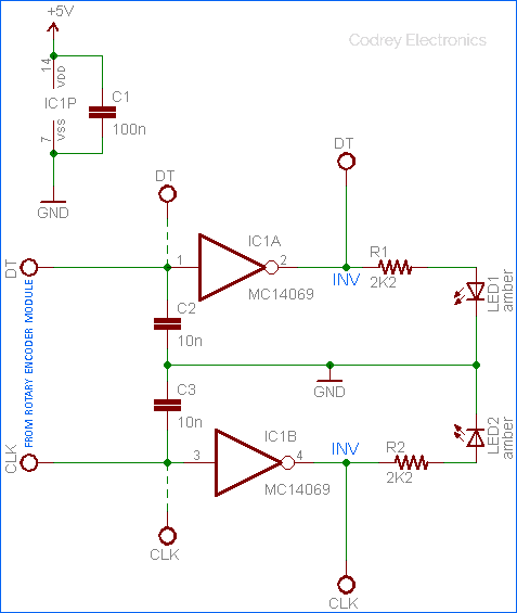
Since one pin of the momentary switch is also linked to the ground rail, the module has a simple 5 pin interface for external connection viz. + (5V), GND (0V), CLK, DT, and SW. The following circuit diagram of the module (prepared by me) will help you to get a clear insight of the construction of the mini rotary encoder module mentioned here. Note that pull-up resistor for the momentary switch is not soldered on the module, so you can see only two 10K pull-up resistors there.
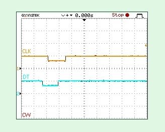
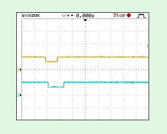
Note that the shaft has unlimited 360 degree rotation, and the shaft rotation is available as electrical pulses that tell in which direction the shaft is rotating. As you can see there are two output pins named CLK (encoder pin A) and DT (encoder pin B) that are used to for reading rotation and when you turn the encoder shaft, switches inside the encoder opens and closes to turn the outputs high (H) or low (L). There will be a pulse pattern at clockwise (CW) operation of the rotary encoder (in the module introduced here) that looks something like the one shown below (a random capture by my oscilloscope).
Quick test circuit for rotary encoder module
Yes, I know that an oscilloscope is not within the easy reach of most electronics hobbyists. Fortunately you can ‘see’ the output signal activity of the rotary encoder by means of the following easy to build circuit. First of all assemble the given circuit and interface it with the rotary encoder module. Then do a quick test by slowly rotating the encoder shaft clockwise (and/or counterclockwise) and observe the LEDs. Remember, the rotary encoder’s shaft have fixed stops so that the shaft stops/clicks at every step of rotation (you will feel a bump). The mini rotary encode module that I have has twenty of these positions.
| (CLK) | (DT) | |
| LED 1 | LED 2 | |
| IDLE | OFF | STATUS=H | OFF | STATUS=H |
| CW | ON (2nd) | STATUS=L | ON (1st) | STATUS=L |
| CCW | ON (1st) | STATUS=L | ON (2nd) | STATUS=L |
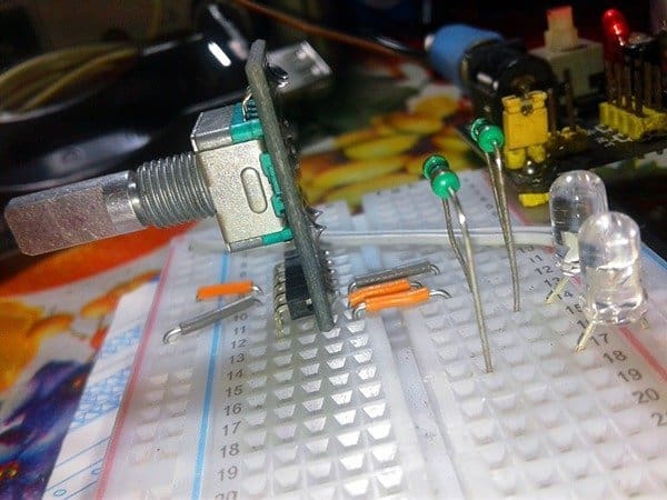
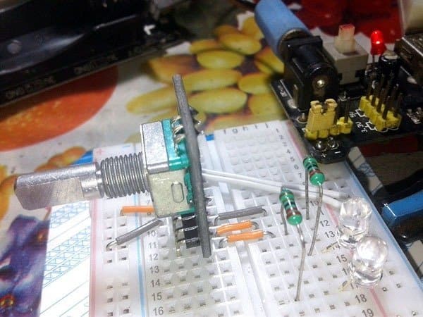
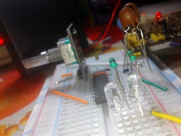
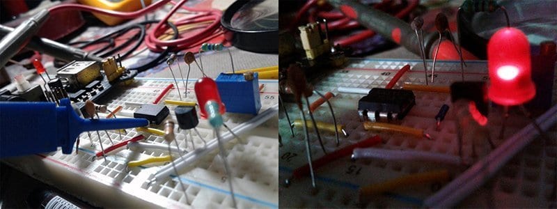
And, see two casual shots of my breadboard setup of the quick test circuit:
Improved hardware interface circuit
Nothing special in this improved hardware interface but it’s merely a hardware debouncer wired around one cheap CMOS hex inverter IC- MC14069 (CD4069). The IC is selected deliberately because it comprises six inverter gates so that you can use the given single circuit for interfacing two rotary encoders. Furthermore, the IC has spare gates still available for building interface circuitry of the momentary on/off switches (four gates for two rotary encoders, and a pair of gates for two momentary switches).
A rotary encoder is a mechanical switch assembly and hence naturally cause a lot of contact bounce. So it’s very hard to decode the output signals correctly. The given circuit will debounce the signal from the rotary encoder and you will get nice clean output pulses (the circuit delivers both non-inverted and inverted rotary signal outputs). I have attempted various values for the capacitors but settled finally with 10nF ceramic capacitors to arrest the unwanted switch bounce noise. Since there are many other clever means of attaining quite clean transitions, I welcome your constructive ideas and suggestions.
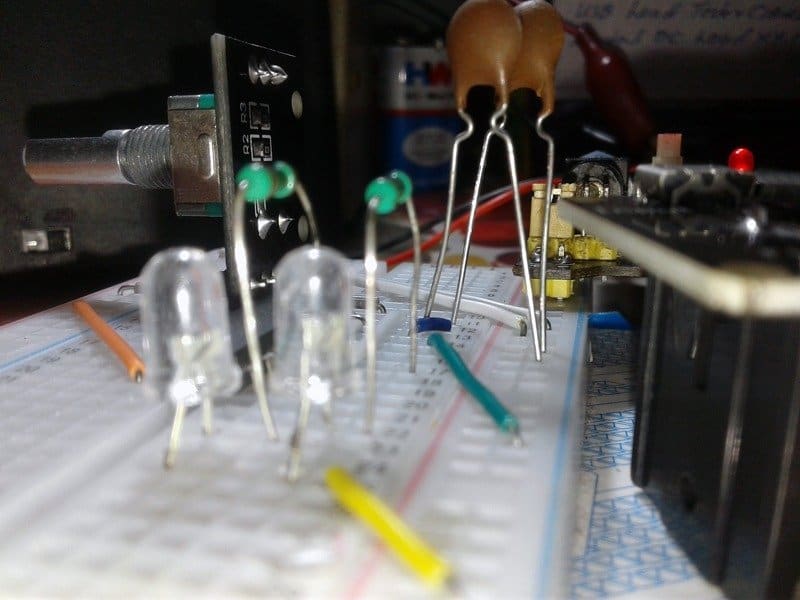
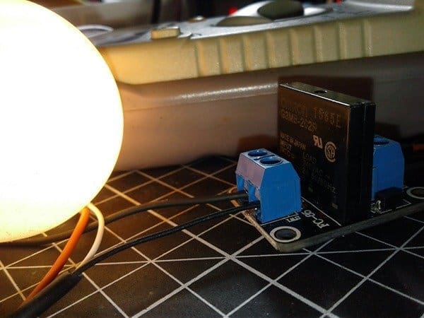
Again, casual shots (this time the improved interface circuit setup) from my workbench:
On a side note, the addition of a Schmitt trigger (rather than just an inverter) will be a clever touch for much more noise immunity. Not having any at hand, I jumped to rig up my first version of the circuit with the MC14069 hex inverter chip. I powered it up and it worked just quite well!
Here’s a random counterclockwise (CCW) rotation capture (sequel of the first oscillogram):
A rotary encoder knob is a pretty great user-input device that you can use to sense rotations left or right and button activation. I have been using rotary encoders in a number of professional projects from time to time since 90s. To demonstrate clearly how a rotary encoder works together with a microcontroller (and how much it’s useful) recently I have developed an ultra-simple do it yourself project. You can see the full-fledged project here with in a couple of weeks!

thanks for this overview but maybe i missed something “CLK (encoder pin A) and DT (encoder pin B)” Why is A o/p tagged as Clock, & B as Data?
Isn’t A signal is exactly the same as the B signal, bar the 90 degrees shift?
@Qtron: When you turn the knob, pins A and B of the incremental rotary encoder come in contact with the common ground pin C, in a particular order according to the knob direction. DT (B) is the same as the CLK (A) output, but it lags the CLK by a 90° phase shift (this output can be used to determine the direction of rotation). And, the CLK is the primary output pulse for determining the amount of rotation (each time the knob is rotated by one click in either direction, this output goes through one cycle of going HIGH and then LOW.
Hope this helps. Thanks for your comment!