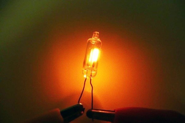
 Neon glow bulb is a nostalgic decorate lamp everybody seems to love. A small version is used still mainly as neon indicator light, also called pilot light, in electric/electronic instruments and appliances as a neon glow bulb generally have a very long life, low current drain and is resistant to shock and vibration. Nowadays, neon glow lamp is experiencing a comeback as an architectural and artistic element, however, independent testing of a neon glow lamp is somewhat difficult because it obviously needs a high-voltage AC supply for the smooth run. Presented here is one battery-operated circuit of a simple and compact regular neon glow bulb (NE-2 style) tester wired around a couple of easy to get inexpensive electronics components.
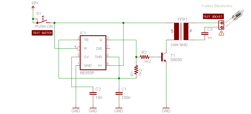
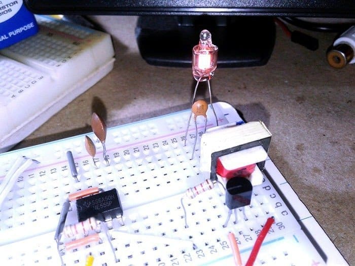
As can seen in the circuit diagram, the design is centered on a NE555P (IC1) timer chip. The 555 timer is now ubiquitous, available on nearly any street corner for just a few coins. Next key component is the good old but quite popular 1300:8Ω small audio output transformer (TFR1) wired here in reverse mode (S:P) like a “tickle stick” inverter-type transformer. IC1 is configured here as a high-frequency pulse generator runs near 6KHz, and TFR1 is driven by its output through a small NPN transistor S8050/SS8050 (T1). RC components R1 (1K2) and C1 (100nF) sets IC1’s oscillator frequency. The entire circuit can be powered from one common 6F22 9V “transistor radio” battery by the push-to-on (momentary) test switch (S1). Note that there’s also one 1nF ceramic capacitor (C3) in series with the 2-pin neon glow bulb test socket.
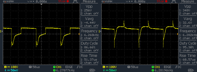
Overall current consumption of the ‘loaded’ tester at 9V dc input is near 200mA. When Vcc is 9.0V, an ordinary DVM will register around 4.6V on the output pin (pin 3) of IC1 (~ 6KHz/60%). Random oscillograms captured while testing a small amber neon glow bulb is included here merely as a reference. You can see output across TFR1’s secondary (left) and output across the neon glow bulb (right) there.
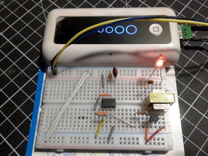
You can ofcourse power up the tester from a 5V dc supply (instead of the 9V), for instance by a mobile phone power bank or breadboard power supply. Refer following table to see the voltage and frequency drifts, as observed in my breadboard prototype.
| DC INPUT | IC1 Pin 3 VOLTAGE | IC1 Pin 3 FREQUENCY |
|---|---|---|
| 9.0V | 4.6V | 6KHz/60% |
| 5.0V | 2.6V | 3.6KHz/75% |
Note over again that the inverter transformer used here is a 1300: 8Ω (ac impedance) small audio output transformer wired in reverse i.e. its original primary is used as the secondary and vice versa. Usually such transformers has a primary coil dc resistance more than 80Ω and around 3Ω for the secondary coil (or so). The primary part is usually marked by a small blob on the top of the bobbin, however, you can use a digital multimeter to key out both the primary and secondary coils. Also take note, the inverter transformer will very quietly sing at 3-6 KHz, that’s normal, but do not touch the output leads of the inverter transformer (test socket). You have been warned!
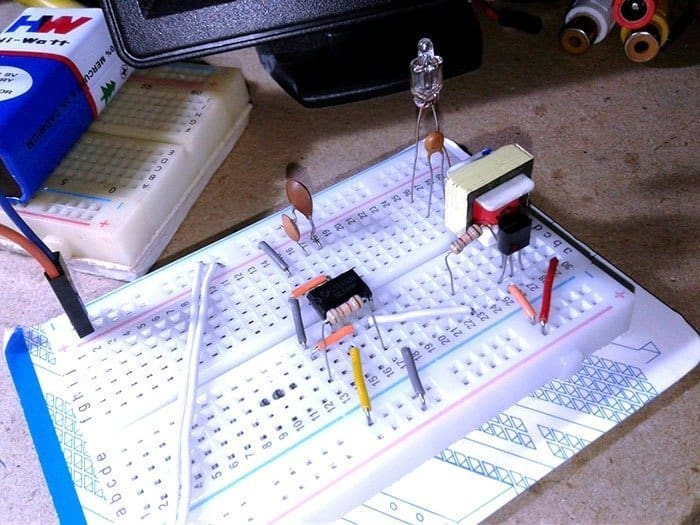
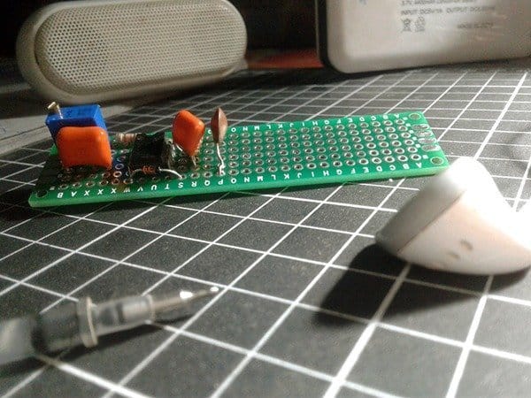
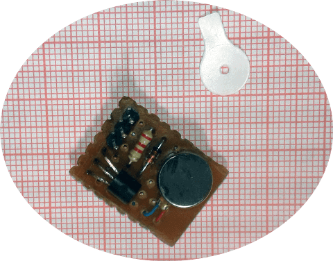
And, to a couple of quick snaps from my workbench:
So I think your schematic is wrong?
Maybe I put it together wrong, but it didn’t work for me.
then I noticed that you had left the discharge pin floating, wouldn’t that stop the 555 from generating the square wave you need?
I rebuilt the circuit by plugging values for the various components into a 555 calculator in order to arrive at the 6khz /~60ish% duty cycle and breadboard’d this new arrangement as a square wave generator driving the transistor and it did work then.
still
thanks for this tutorial
(for those following along, Set up in astable mode: 1k ohm from v+ to pin 7, 1.5k ohm from Pin 7 to Pin 6, and 60 nF from Pin 6 to ground)
TonyTickles: Thanks for the contact!
The schematic is 100% correct. As you can also see in the pictures of my breadboard setup, Pin 7 of the 555 IC is not used here!
In this simplest 555 free-running oscillator circuit, Pin 3 of IC1 is directly wired to the timing capacitor C1 via a single resistor R1 as shown. Since the capacitor C1 charges and discharges through the same resistor R1, the duty cycle of this simplistic setup is very close to 50%. And, the output waveform frequency is equal to 0.722/R1C1.
I’m glad to see your efforts to follow my little design idea. Good luck!
.
Thanks for the reply! I just tried this out in a simulator and the simulator liked it, so I must have done something wrong on the breadboard.
I’m probably too slow for this stuff haha
thanks for all the excellent content you’ve posted by the way!
Hello T.K.Hareendran
Thanks for this article I found it very helpful.
One question, I read that powering these bulbs using a DC power source effectively halves their life, is that true?
Thanks
Mugen: Thank you for your interest in my article.
Coming to your question, I haven’t read anywhere about this issue yet. No matter, I’ll do a deeper investigation later. BTW, you may have already noticed that when driven from a DC source, only the negatively charged electrode (the cathode) of a neon bulb glows.
Thanks for your reply.
I was wondering about why only one electrode appeared charged, but that makes sense regarding a DC vs AC power source.
I saw the mention of diminished life expectancy on the datasheet for the ne-2 bulb actually. It’s on the bottom of page 66 (page 1 of this preview pdf) on this datasheet:
https://www.datasheetarchive.com/pdf/download.php?id=f2f14d4fe07a4cae3359b12c769629d285d6d4&type=O&term=NE-2%2520neon
Mugen: Thanks for sending the link. I went through the datasheet and read the footnote on page 66. To me, that note is a little confusing, but I’ll cross-reference a few NE-2 neon lamp datasheets and keep you posted.
(may be a good read at this time https://www.intl-lighttech.com/instrumentation-sensor-light-sources/neon-lamps)
Coming to DC: AFAIK, while in DC, the neon ion picks up an electron at the negative electrode shifting back to normal neon gas, and that process produces a photon of light which glows at the negative electrode. But both electrodes glow during AC operation as the rhythmically changing polarity of AC naturally reverses the negative electrode.
All feedback is valuable and important!
Thanks again for the reply and the link, that’s a good read!
I was thinking the same regarding the reversing of polarity with AC making both electrodes seemingly glow at the same time. I suppose they would be flickering at 50/60hz actually, probably capturable on a camera.
Thanks for the great blog!