In this post, I will take a quick look at making traffic light projects. The model project will involve using only a little bit of affordable hardware that’s great for beginners and school students. Even though the thoughts posted here are extremely basic, it might a nice way to get something that helps you build your own awesome automatic traffic light systems.
As clearly pointed in the title, the project introduced here is mainly based on a prewired “Traffic Light LED Module” available all over the web with a cheap price tag. In the pretty little LED module, usually, you can see three big (10mm) LEDs – one Red, one Yellow, and one Green – together with three independent current limiting resistors. Recommended working voltage of the module is in 3.3V to 5VDC range – yup, really a common microcontroller compatible device.
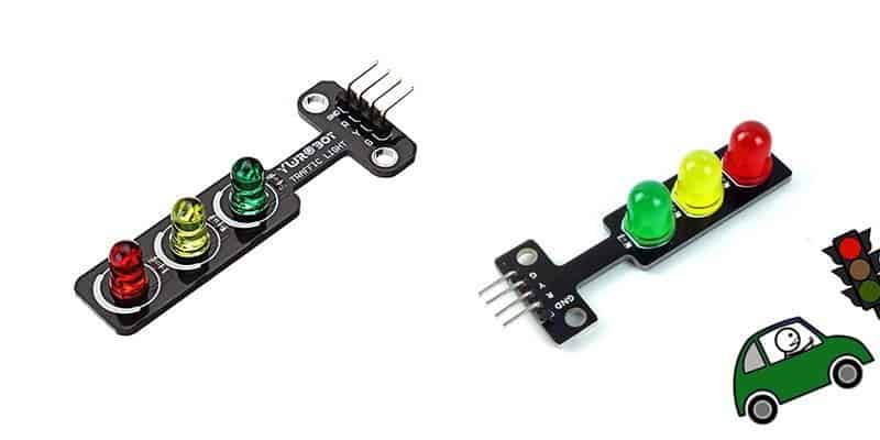
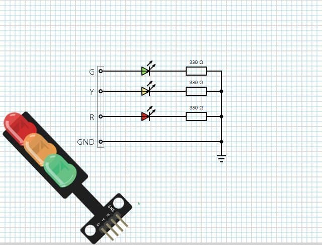
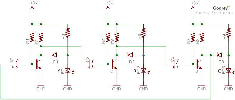
As at all times on Chinese electronics, sellers had a variety of traffic light LED modules in stock, but usually use the red (stop), yellow (alert), and green (go) LEDs. This is the schematic diagram of the traffic light LED module I bought from an Indian online electronics retailer.
Just a side walk
Across the web, there are countless circuits for do it yourself simple traffic light projects. Many are very crude, using nothing more elaborate than a couple of common and inexpensive discrete components, while others are very luxuriant indeed. For example, here you can find a simple traffic light project with just two 555 timer ICs https://www.bitsnblobs.com/traffic-lights-555-timer-b2p9/. Similarly, here’s another toy traffic light project wired around one PIC16F1823 microcontroller www.digiwood.ee/8-electronic-projects/8-toy-traffic-light.
Sure, you can also find a vast range of unassembled and assembled cheap mini traffic light kits everywhere you go. Most of them are ‘desktop’ models for simple demonstrations.
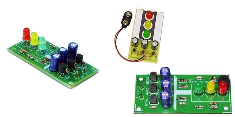
The above figure depicts three variants of the quite popular mini traffic light kit for kids/school students, designed to run on a standard 6F22 9V battery. Actually, all editions follow the same electronic circuit which is an extremely simple one based on just three transistors and a couple of other discrete parts. By referring the basic sketch shown below you’ll get an idea about how it’s formulated by the clever designer. It’s unusual but look, values of components are not tagged – that’s intentional because of some limitations, and I regret for that.
Arduino & Traffic Light LED Module
In this session, we will take a look at making a simple Arduino traffic light. Here, the Arduino board drives the traffic light LED module directly, and works with 9V. First of all, wire the Arduino board and the traffic light LED module together as keyed in the table below.
| Arduino Board | Traffic LED Module |
|---|---|
| D13 | R |
| D12 | Y |
| D11 | G |
| GND | GND |
Next, copy-paste the Arduino Sketch (code) provided below into the Arduino IDE and upload it to your Arduino board. The sequence will then begin!
int GRN = 11;
int YEL = 12;
int RED = 13;
int DELAY_GRN = 6000;
int DELAY_YEL = 2000;
int DELAY_RED = 6000;

void setup()
{
pinMode(GRN, OUTPUT);
pinMode(YEL, OUTPUT);
pinMode(RED, OUTPUT);
}

void loop()
{
GRN_light();
delay(DELAY_GRN);
YEL_light();
delay(DELAY_YEL);
RED_light();
delay(DELAY_RED);
}


void GRN_light()
{
digitalWrite(GRN, HIGH);
digitalWrite(YEL, LOW);
digitalWrite(RED, LOW);
}
void YEL_light()
{
digitalWrite(GRN, LOW);
digitalWrite(YEL, HIGH);
digitalWrite(RED, LOW);
}
void RED_light()
{
digitalWrite(GRN, LOW);
digitalWrite(YEL, LOW);
digitalWrite(RED, HIGH);
}
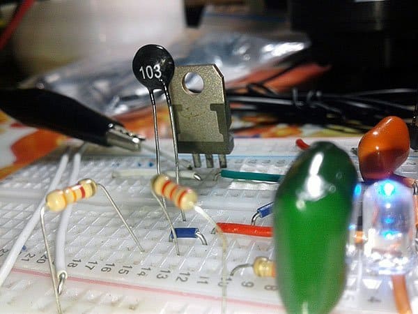
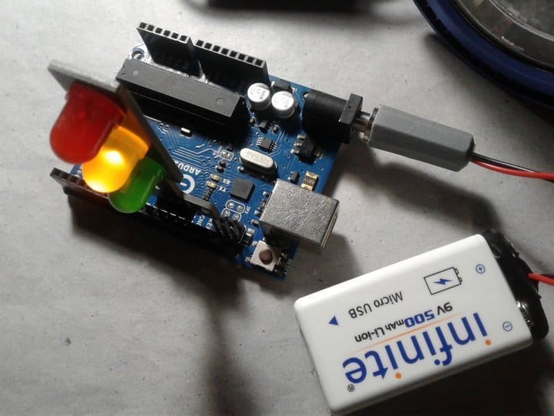
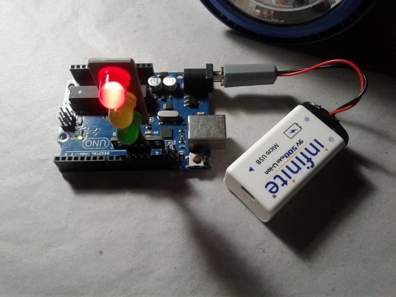
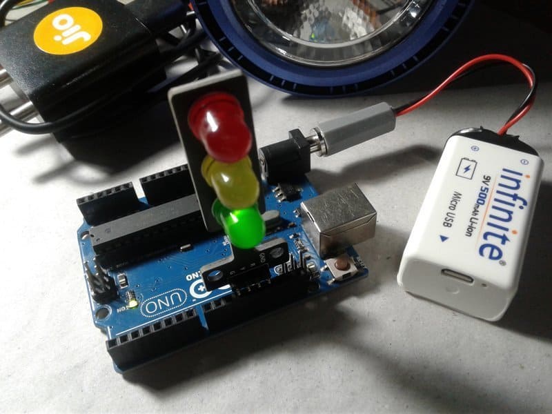
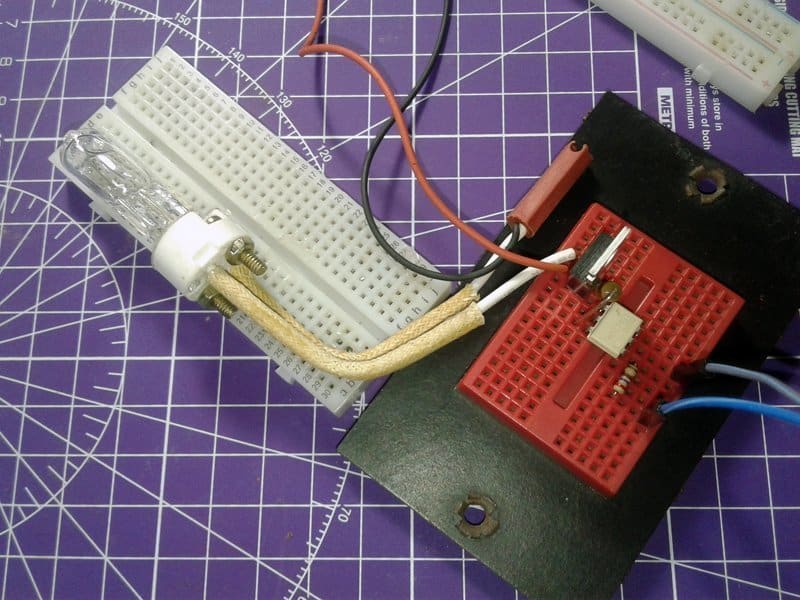
Like it? Well, now you can modify the basic example code for other elegant traffic light system projects and experiments. A different time can be given to each sequence of lights if desired. The code could also easily be expanded to add more lights/features. Give it a good try! Below is a couple of random snaps from my workbench.
AC230V Traffic Light Driver
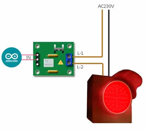
A couple of times I found hobbyists would like to build the traffic lights with candent lamps and/or LED arrays. I then needed to work out how to drive AC230V traffic lights. This is the simple solution that I ended up with:
The Arduino can of course drive electromagnetic or solid-state relays through small driver transistors to switch mighty electric loads, but I don’t want to make iterated ‘clicks’ and/or sparks. Just because I opted for the above triac switch solution, a bit cheaper than using solid-state relays (SSRs). Beware, AC230V can be fatal, both to yourself and to your entire electronics. Follow the appropriate precautions. I make no claims about the safety of this circuit.
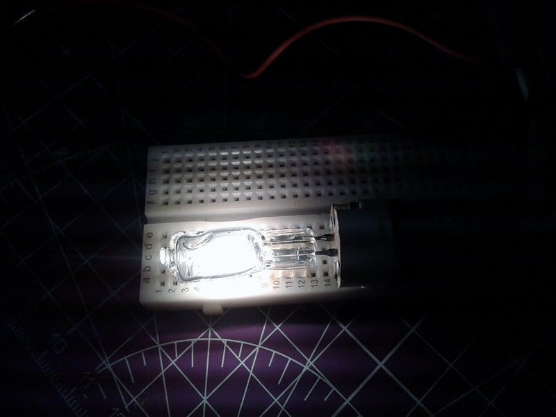
Quick test shots (AC230V/40W Halogen Bulb):
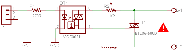
For driving incandescent lamps, the above circuit can be used. The main restriction is that the triac must be properly chosen to sustain the proper inrush loads as incandescent lamps can sometimes draw a peak current known as “flashover” which can be extremely high, and the triac should be protected by a fuse or rated high enough to sustain this current. According to NXP datasheet, BT136-600D is a very sensitive gate four quadrant (4Q) triac intended for use in general-purpose bidirectional switching and phase control applications, where high sensitivity is required in all four quadrants. This ‘series D’ triac can be interfaced directly to microcontrollers, logic integrated circuits, and other low power gate trigger circuits.
Below you can see the proposed wiring diagram for a single traffic light channel. Needless to say, you’ll need to rig up two more similar triac switch circuits to drive the next two traffic lights.
Triac Driver Maths
Now to a snatch of napkin back calculations: The MOC3021 is an optically isolated random phase triac driver device. Here, the preferred value for its emitter series resistor (R1) is 270Ω. In principle, this resistor should be chosen to set the current into the opto device to be a minimum of 10mA (15mA typical). Assuming the typical forward drop to be 1.5V at 15mA allows a simple formula to calculate the emitter series resistor: R1 = (5V – 1.5V)/15mA = 233Ω.
Coming to the value of the series gate resistor (R2), it’s in fact a mere tradeoff between limiting the peak current through the opto device, and allowing enough gate current to turn on the triac. From the Fairchild application note, maximum surge current rating (ITSM) of MOC3021 sets the minimum value of R2 through the equation: R2 (min) = Vin(pk)/ITSM.
As found in the datasheet, the maximum surge current rating of MOC3021 is 1A. The peak voltage for a 230VAC line is 230 x 1.414 = 325V, so R2 = 325V/1A = 325Ω minimum. At 230VAC, you can rounded it to 330Ω for a standard value. The power dissipation of the gate resistor R2 will be down, but a ½ watt (500mW) resistor seems fine. However, while crawling along the web for triac switches, you may have come across a large deviation in the value of the series gate resistor. Anyway I would advise against using very small value resistor there although by calculation it may be right. As you can see, in my schematic I employed a 1.2KΩ resistor (R2) which might restrict the current to 270mA.
Further Learning – https://www.onsemi.com/pub/Collateral/AN-3003.pdf.pdf
Next Experiment
Next inline is the design and development of a pedestrian interactive multichannel traffic light system, perhaps with a wireless control button, too. I’m not going into it immediately. Let’s make a break now and continue later with that more novel idea. Enjoy your time!