Nostalgia is often caused by something that reminds you of a happy time. Is it not so?
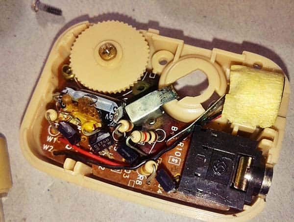
Oh, I’m not into nostalgia, but looking back to find some wonders from the past. So, let me start this quick post by picking a funny commercial device from my good old analog electronics collection. Well, now you can see the little gizmo – Spy Ear iSpy007!
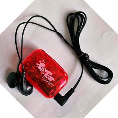
What’s this astounding device? This device is in fact a powerful secret audio amplifier with a built-in high-sensitive microphone, which’s similar to the simple hearing aids you’ve may have seen advertised on teleshopping channels. As advertised, it’s a fun toy for kids and a useful tool for adults.
Just plug in the earphones and turn on the device, adjust the volume knob to your comfort level, and you’re ready to go. You can wear it at your side and amplify all sounds around you, or you can aim the microphone at a source to amplify specific sounds up to 40 decibels (40dB).
As usual, a teardown report of this device will be published later. At this point, I’ll show you how to make a simple spy ear using a few easily available parts around you. Inspired by an illustrious smartphone app (https://play.google.com/store/apps/details?id=superhearing.app), this spy ear is provisionally named Economic Ear Scout.
As it seems, basic electronics behind a common spy ear/hearing aid is nothing but the clever combination of a battery-powered electret microphone preamplifier and a monoaural headphone amplifier circuitry realized with the help of some discrete electronics parts (https://www.codrey.com/electronic-circuits/hearing-aid-diy-kit/). However, the economic ear scout project presented here uses a bit different technique as the design is centered on a fancy electret microphone module with MAX9814 IC at its heart (see below).
- MAX9814 Datasheet https://datasheets.maximintegrated.com/en/ds/MAX9814.pdf
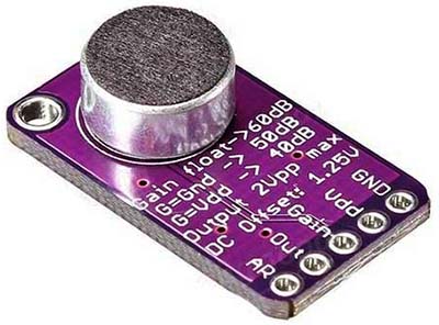
This minuscule module has a built-in automatic gain control (AGC), so the nearby loud sounds will be hushed, and far-away sounds will be amplified gently. Therefore, this module is great for when you want to detect or record audio in a background where signal level changes out of the blue and you don’t want to have to tweak the amplifier gain all the time.
The module has a 2.7V to 5.5V dc supply voltage range. The default maximum Gain is 60dB but can be set to 40dB or 50dB by linking the Gain pin to Vdd or GND. You can also modify the Attack/Release (AR) ratio, from the default 1:4000 to 1:2000 or 1:500.
The maximum output from the module (Out) is around 2Vpp. The output, however, is not enough to drive loudspeakers or anything but the smallest in-ear headphones. When you want to route it into the “Line” input of an external audio amplifier, use an appropriate capacitor in series to “AC-couple” the audio signal.
Note that the output of the MAX9814 is biased at 1.23V. So, to eliminate the DC offset, the AC-coupling capacitor (COUT) is absolutely essential. Depending on the input resistance (RL) of the following stage, COUT and RL effectively form a high pass filter. The -3dB point of the high pass filter, assuming zero output impedance, is given by:

(The -3dB point is very commonly used with filters of all types. The frequency at which the power level of the signal decreases by 3dB from its maximum value is called the 3dB bandwidth. A 3dB decrease in power means the signal power becomes half of its maximum value).
Back to the Economic Ear Scout project, below you can see its schematic diagram.
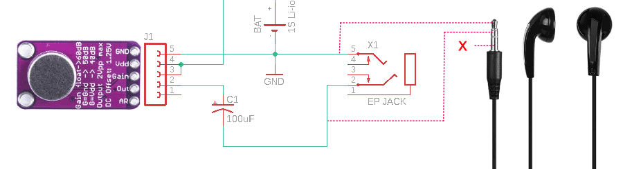
The ear scout is a simple device ready to be operated at around 3.7V, so, it can be powered by a single-cell lithium-ion battery (1S Li-ion battery). If you think you might accidentally start connecting the battery the wrong way round, it’d be better to put a small Schottky diode (https://www.electronics-tutorials.ws/diode/schottky-diode.html) in series with the battery connector, or you’ll smoke your MAX9814 module.
This battery-operated system amplifies the output signal of an electret capsule microphone to audio line level. It has an excellent overload margin and can cope with anything from a whisper to a loud cry, however, the earphones you connect to its output too can be deluged, so the default gain is set to 40dB. You can use a pair of 32Ω earphones (wired in series) to listen to the audio.
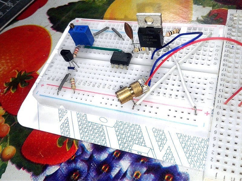
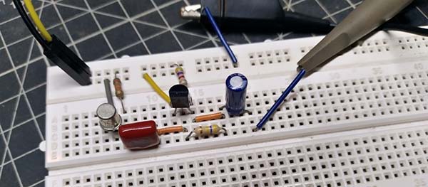
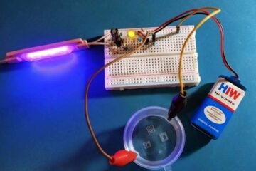
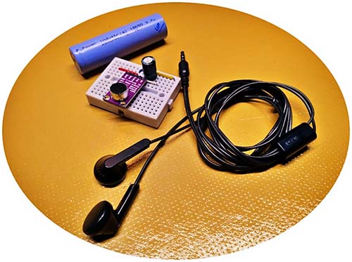
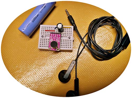
I made a quick test setup on a mini breadboard and used a smartphone stereo earphone at its output to hear the sound. It worked as expected and gave excellent outcomes!
On a related note, the schematic above shows the wiring method for a TRS (Tip-Ring-Sleeve) stereo earphone, but a smartphone stereo earphone/headset usually has a TRRS (Tip-Ring-Ring-Sleeve) plug at its end. Below is its wiring pointer.
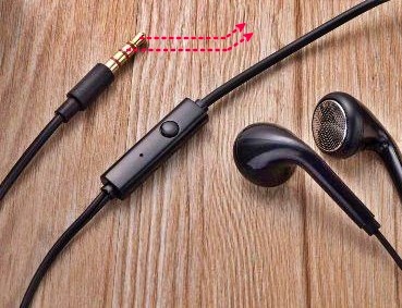
Now it’d be better to pay attention, to the 3.5 mm stereo earphone jack used here (refer to the schematic), when the stereo plug is not present, the switches, which are formed by 2 & 3 and 5 & 4 are closed. When the 3.5mm stereo audio plug is inserted, these switches are open because the stereo audio plug bends 2 and 5 slightly, and break the contact with 3 and 4. Naturally, the output of the MA9814 module is connected to the Tip and Ring of the stereo earphone through pins 2 and 5.
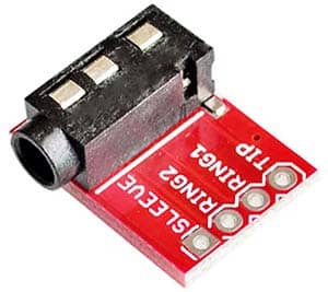
Needless to say, a TRRS 3.5mm jack breakout board will make your breadboard construction much easier!
I won’t go into the construction details of an enclosure for this project, as it’s not a serious job. Ideally, try to use a 3D printed box, as it’ll give your device a professional look. Likewise, the lithium-ion battery charger circuit is not included, but you can see some cool ideas elsewhere on this site.
That’s all for now! Give this little project a try for yourself. It’s my pleasure to have your suggestions!