The Funny TV Faker project presented here is in fact a portable TV Light Simulator. A commercial television light simulator device has a bunch of flashing and flickering lamps to simulate the light of a real television. Thus, it gives the appearance of someone is watching television!
A television light simulator can make your house look occupied because when positioned correctly in a room, it will render the effect of someone watching television inside to anyone who happens to be standing outside. A thief would more than likely not take any chances, leave your house and hopefully just go onto your neighbor’s (most prowlers do not aim at occupied houses as they usually like to move on to easier targets)!
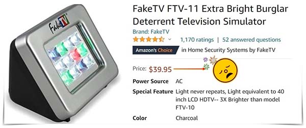
A while ago, I saw many similar gadgets in online stores and I found the idea behind them very interesting. Since I didn’t want to pay around $40+ for a simple toy, I planned to build one using readily available components. Below are the project details of that little device – Funny TV Faker. Enjoy!
With a view to go with more extensions in the future, I picked a tiny microcontroller as the little brain of my project. Following the same thought, the light panel was made using smart light-emitting diodes.
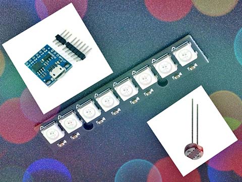
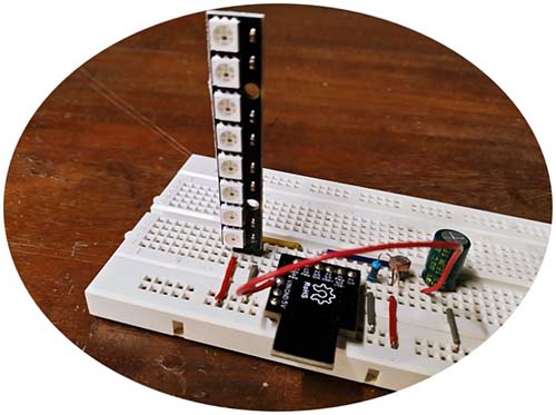
So, these are the key elements you need to gather to begin your project:
- NeoPixel Stick (WS2812-8 RGB LED)
- Digispark Attiny85 Development Board (original or clone)
- GL5528 LDR x1
First off, upload the below code to your Digispark board. The given code is a mere adaptation of an idea once presented by Marcus Jenkins. My setup and pixel transitions are not great, but to some extent, they can mimic the live screen of a television!
#include <Adafruit_NeoPixel.h> // NeoPixel Library

#define PIN_NEOPIXEL_OUT  0 // P0 of Digispark
#define ADC_LDR           1 // P2 of Digispark

#define NUM_LEDS  8 // NeoPixel LEDs x8

#define LED_BRIGHT  120

#define LIGHT_THRESHOLD 325 // See Notes!
#define DARK_THRESHOLD 320

typedef struct
{
  int period;
  int r;
  int g;
  int b;
} FAKE_PICTURE;

FAKE_PICTURE pictures[] =
{
  {1000, LED_BRIGHT, LED_BRIGHT, LED_BRIGHT / 2},
  {2000, LED_BRIGHT, LED_BRIGHT / 2, LED_BRIGHT},
  {4000, LED_BRIGHT, LED_BRIGHT, LED_BRIGHT},
  {2000, LED_BRIGHT / 2, LED_BRIGHT, LED_BRIGHT},
  {2000, LED_BRIGHT, LED_BRIGHT, LED_BRIGHT / 2}
};


Adafruit_NeoPixel strip =
  Adafruit_NeoPixel(NUM_LEDS, PIN_NEOPIXEL_OUT, NEO_GRB + NEO_KHZ800);

void setup()
{
  strip.begin();
  strip.show();
}

void loop()
{
  static boolean isNight = false;
  static int pictureIndex = 0;

  int ldrValue = analogRead(ADC_LDR);

  if (isNight)
  {
    if (ldrValue >= LIGHT_THRESHOLD)
    {
      isNight = false;
    }
  }
  else
  {
    if (ldrValue <= DARK_THRESHOLD)
    {
      isNight = true;
    }
  }

  delay(pictures[pictureIndex].period);
  if (isNight)
  {
    setLEDs(pictures[pictureIndex].r, pictures[pictureIndex].g,
            pictures[pictureIndex].b);
  }
  else
  {
    setLEDs(0, 0, 0);
  }

  pictureIndex ++;
  if (pictureIndex >= sizeof(pictures) / sizeof(pictures[0]))
  {
    pictureIndex = 0;
  }
}

void setLEDs(int r, int g, int b)
{
  uint32_t colour = strip.Color(r, g, b);

  for (int i = 0; i < NUM_LEDS; i++)
  {
    strip.setPixelColor(i, colour);
  }

  strip.show();
}
And then, gear up your hardware as indicated in the simplistic schematic shown below.
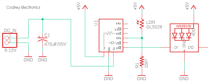
Since this circuitry is tailored to be powered by an external 9-12VDC source (500mA minimum), you can use suitable wall warts or battery packs as the power source. The NeoPixel stick is powered by Digispark’s onboard voltage regulator (78M05) which can cater ample current to make the light stick happy.
During an experimental run, it’s casually observed that the NeoPixel stick normally draws around 120mA of current, and with the pixels displaying white at maximum brightness, it shoots up to about 340mA.
Oh, and on a side note, the commonly recommended 330-470Ω resistor on the link between the microcontroller‘s I/O and DI of the first NeoPixel (to dampen backlashes) is not crucial in this circuit but it won’t hurt!
At this point, be aware of it, some clone Digispark boards with micro-USB connector (look again at the picture of the key elements) usually holds a 78L05 onboard voltage regulator. If so, you may need to alter the above design to employ an external 5VDC power supply. Remember, you can power your Digispark up with the USB port, or by wiring your 5VDC power supply to the 5V and GND pins, or by wiring a higher voltage (≥7.4VDC) power supply to the VIN and GND pins.
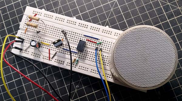
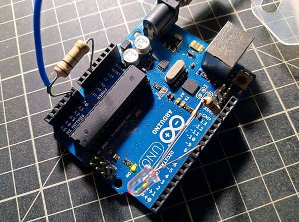
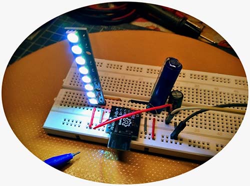
Casual snaps of my unpowered breadboard prototype:
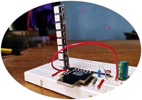
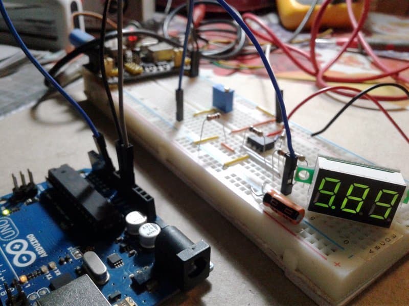
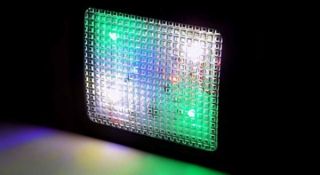
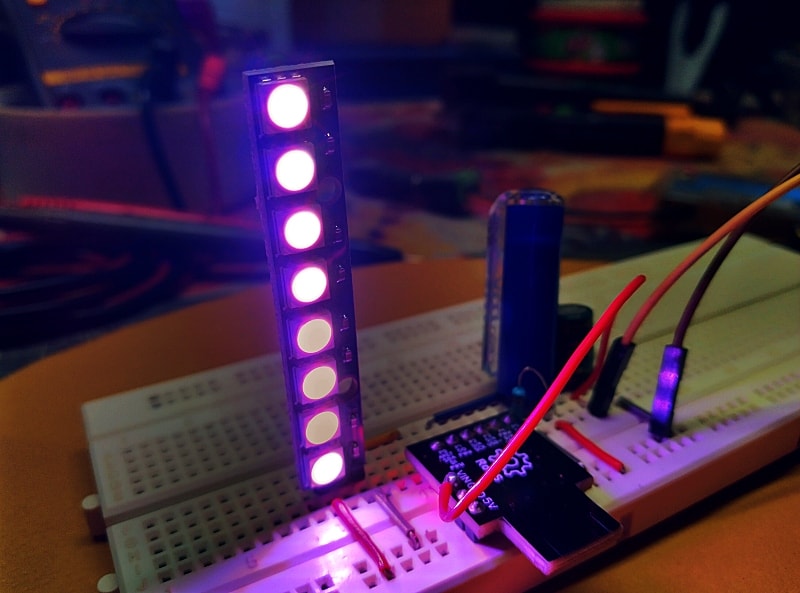
For the agile test, I powered my breadboard setup with a rechargeable 9V USB battery, and it worked well as anticipated. The LDR was covered with an opaque pen cap at that daytime to hinder surrounding light from falling on its face. Below is a live test shot taken by a smartphone camera.
In this design, the photoresistor is wired in a way that the value read by the analog input pin will actually increase as the ambient light increases. The potential divider setup lets more current pass through the photoresistor to the analog input pin which results in a higher value reading during the daytime, and vice versa.
Note that the light (day) and dark (night) detection threshold values in the code will probably need minor refinements in your project. So, play a little with them and see what the values work for you. Or replace the 10KΩ resistor with a multiturn 50-100KΩ trimpot (feel free to use a bit lower or higher value trimpot) to finetune the threshold values through empirical observation.
LDR, also known as a photoresistor, is a variable resistor that produces a resistance proportional to the amount of light it senses. By adding another resistor to the photoresistor we can create a voltage divider.
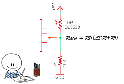
In principle, a voltage divider involves applying a voltage source across a series of two resistors. Here, the resistor closest to the input voltage is the LDR and the resistor closest to the ground is R1. And, the voltage across the resistor R1 is the “output” voltage (divided voltage) that goes to the analog input of the tiny microcontroller. This output voltage is directly proportional to the input voltage and the ratio of LDR and R1.
Just assume that the “light resistance” of the photoresistor is 1KΩ and its “dark resistance” is 10KΩ. Then, with R1 as fixed 10KΩ, the ratios and output voltages are as shown in the below table.
| Light Level | Ratio | Output Voltage (5V) |
|---|---|---|
| Light | 0.9 | 4.5V |
| Dark | 0.5 | 2.5V |
Note that there is a voltage swing of about 2V which is an acceptable resolution for most analog-to-digital converters (https://learn.sparkfun.com/tutorials/analog-to-digital-conversion)!
On a thought about its enclosure, the final model could take the form which fits your real needs or your imagery. Just a hint – you can put the entire assembly in a translucent plastic/acrylic box with the NeoPixel stick mounted on its forepart (remember to orient the photoresistor aright).
As always, there is room for big improvements, and of course, your own subjective ameliorations may always be made. Finally, your support in disseminating electronics knowledge is greatly appreciated. I hope you share the link of this post with others on social media as well.
Addendum: RGB or RGBW NeoPixel?
From what I have figured out, the RGB NeoPixel LED has 3 colored pixels while the new RGBW version has 4 as there is a dedicated while pixel too. The RGBW type (https://www.digikey.com/catalog/en/partgroup/neopixel-digital-rgbw-led-strips/59789) however uses a different controller – SK6812 – but it looks like the actual protocol is very similar except for having 32 bits per LED instead of 24.
![]()
I’ve Googled for and got the SK6812RGBW datasheet (http://www.szledcolor.com/download/SK6812RGBW.pdf) which denotes that it’s already fully supported by the recent Adafruit Neopixel library. However, the RGBW type demands a comparatively much higher current when all colors are at maximum brightness!
More about this in detail will be covered in a future post