Sometimes you may need ready-made hardware to set up a simple timer to help you control something at the right time. No wonder, Chinese electronics have many instant solutions for that, the simplest of which is the 555-timer module. As usual, there are many variants, but this post is about a cheap “NE555 0-10S Delay Timer Relay” module I came across recently.
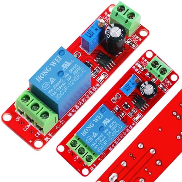
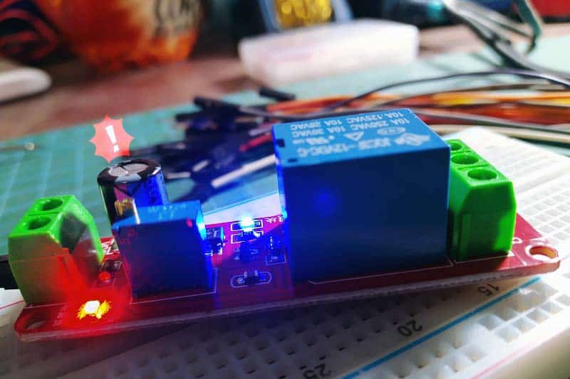
This is a 12VDC operated monostable module based on the NE555 timer chip. It features an adjustable turn-on delay time from 0 to 10 seconds which can be set through a multiturn trimpot. Also there is an onboard AC250V/10A (DC30V/10A) rated relay for driving external AC/DC electrical loads.
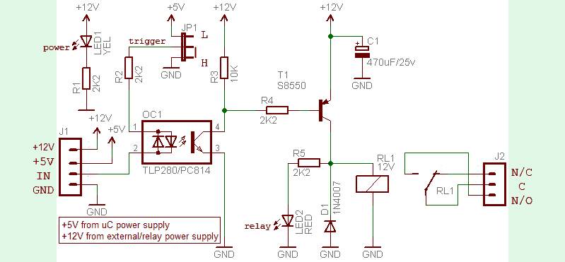
Also, the module has two LEDs – red for power on indication and blue for timer on indication.
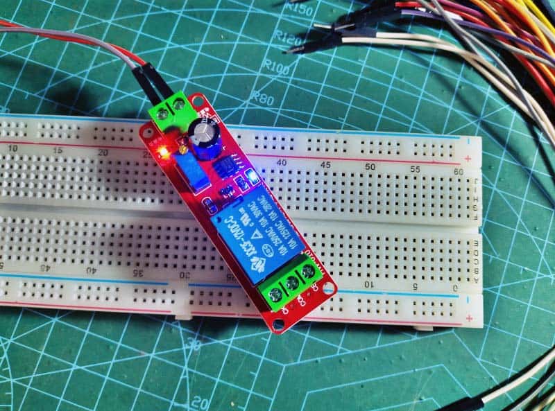
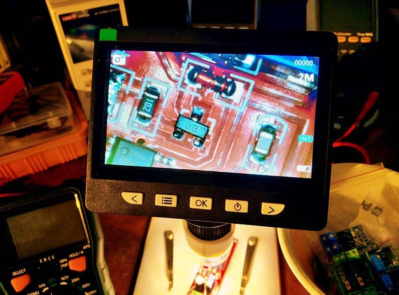
Out of curiosity, I carefully poked into the module, studied its PCB layout, and finally made a circuit diagram of it.
At the same time, I got its schematic from a Chinese seller (see below).
Note at this point that I have edited it slightly to correct some mistakes, and to ensure better clarity.
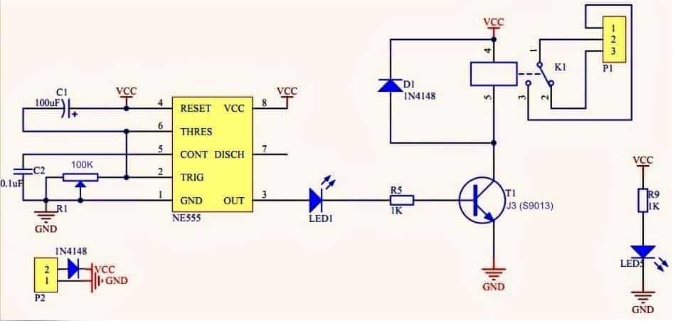
As a side note, it is not a hard task to alter the turn-on delay by changing the value of the 100K trimpot (R1) and/or the 100uF electrolytic capacitor (C1) if you have enough dexterity. However, the latter is relatively easy even for novices.
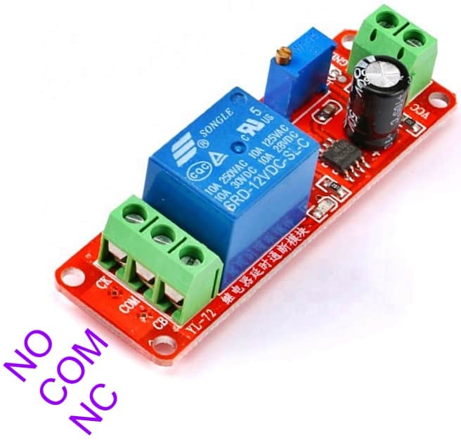
Also, the relay output points in some modules are marked strangely as CK-COM-CB, where the COM is obvious. If so, just note that CK & CB are the NO & NC connections (see below).
Not to mention, this is an 0n-delay timer module. As its name suggests the timer contacts changeovers after some delay i.e. after reaching the preset time (on delay time) the timer relay’s close contacts (NC) open and open contacts (NO) close. When the timer’s power supply is removed, the contacts return to their original state. A simplified timing diagram of the on-delay timer is shown below.

Let me conclude this little post with a bit of advice…
In many 555 cookbooks, designers talk about the 555 being a nasty chip with undesirable spikes on its power rails. A proven solution to this is to put a buffer capacitor across the power supply rails (Vcc-Gnd) to decouple the timer chip from the power supply. Usually adding a 220nF tantalum bypass capacitor (together with a 47uF or 100uF capacitor) directly adjacent to pins 8 and 1 of the timer chip will be sufficient. If you do not put in the bypass capacitor(s) to mitigate the spikes, you may find other segments of your system behave badly depending on how large the spikes on the power rails are and how sensitive the related circuitry is to those spikes!
Well, in my book, this is a pretty simple and cheap delay timer relay module with no serious design flaws. However, there is still room for some improvements. I will not jump into that today – YGWYPF (you get what you pay for) 😀
WARNING! Do not attempt to use this module unless you know what you are doing! There exists a possible danger of electric shock which can be fatal. There are some bare solder points in the circuit board that carries live AC and you must not touch them ⚠
Hi and thanks for this article!
Could you please give some hints how to mod this module to work as flasher (similar to mentioned in “Multipurpose Power-Thrifty LED Flasher”) switching on/off load through the relay?
To answer a perplexing question… Why were the abbreviations CK and CB used?
In Chinese, Cháng Kài (CK) means Normally Open (NO) while Cháng Bì (CB), means Normally Closed (NC).
Mike: Really great and useful information. It’s something that many people don’t pay much attention to. Thanks!
@Max: In my view, hacking such a small and cheap Chinese module would be a waste of effort. Better, build yourself a new 555 IC based astable circuit. Countless circuit ideas are available all over the web. See a good example https://www.nutsvolts.com/magazine/article/555-astable-circuits Thanks!
I need a relay that is in the Normally Open state at rest and when pressed, closes the circuit for 5 seconds and returns to the NO state. Is this circuit valid?