The LM385 is a micropower two–terminal bandgap voltage regulator diode. It is designed to operate over a wide current range of 10mA to20 mA, and features exceptionally low dynamic impedance, low noise and stable operation over time and temperature.

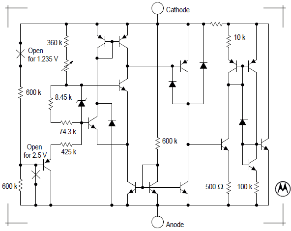
The LM385 is a so-called shunt reference. It works in series with an external resistor, allowing enough current to flow through it to get a fixed voltage across its terminals. For example, the LM385Z-2.5 device has a reverse breakdown voltage of 2.500V with ±3.0% tolerance at 0° to +70°C operating temperature range, whereas it is 1.235V ±2.0% for the LM385Z-1.2 device. Below you can see its representative schematic diagram.
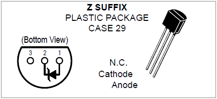
And, below is the pinout data of the Z suffix plastic package (CASE 29).
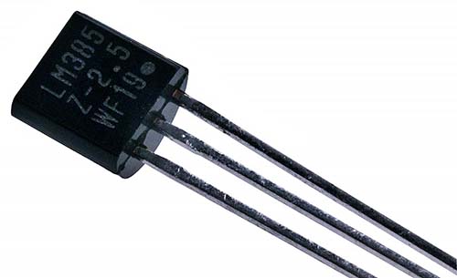
Voltage references have a major impact on the performance and accuracy of analog circuits. Ever since my first project completed in the 90s, I have been a die-hard fan of LM385 series chips and even last week I acquired a good assortment of them from an Indian online store.
OK, now let us look at the 2.5V version of the LM385 in more detail (https://www.ti.com/lit/ds/symlink/lm385-2.5-n.pdf).
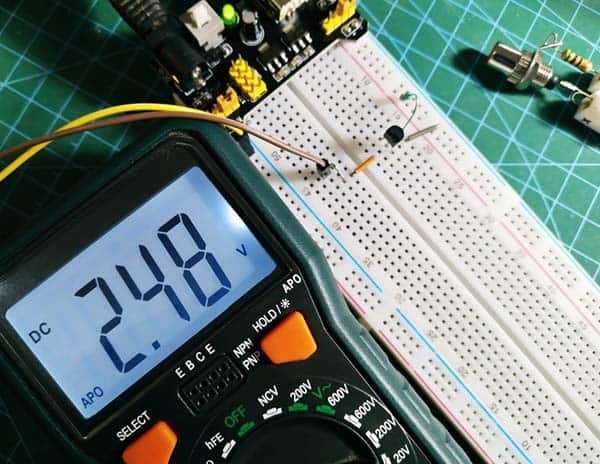
Below simple scheme demos how to obtain a reference voltage of around 2.5V from the LM385-2.5 chip.
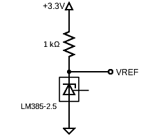
Note that this is a shunt regulator thus to maintain regulation a minimum current of 20µA must be able to flow into the LM385-2.5 chip. But it must never be outside the range of 20µA-20mA, otherwise the LM385-2.5 will stop working properly. Also keep in mind that the pull-up voltage has to be greater than the 2.5V of the device.
In practice, there are simple techniques for obtaining a voltage reference, such as using zener diodes, sometimes the degree of precision required for an application may demand much more elaborate configurations. Then we can count on a good deal of dedicated voltage reference ICs, now we have one of them – the LM385 series.
Now note that the LM385 version, without suffix, has an adjustment terminal and can operate in two basic configurations as delineated in its datasheets/application notes (https://www.ti.com/lit/ds/symlink/lm385-adj.pdf).
And nothing more, in the first, it operates as a fixed voltage reference which is given by the band-gap regulator while in the second case, it is possible to program the output voltage to a higher value with the help of a resistive divider. Here is the link to a related post published last year https://www.codrey.com/electronics/lm336z5-ic/.
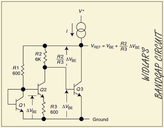
Back to the roots, since its inception in the late 1960s, the simple and robust bandgap circuit has served as a key element in most integrated circuits. A bandgap voltage reference is a voltage source that outputs a voltage proportional to the bandgap of a semiconductor. The SI bandgap voltage (Silicon) references are most common (which output at about 1.2V). Bandgap voltage references are widely used in electronics to generate stable voltages that do not change with temperature. The idea was first debated by David Hilbiber in 1967, but first used commercially by the wandering electronics genius Bob Widlar in 1971.

Although Bob Widlar’s voltage reference laid the foundation for today’s bandgap references, it had current drive sensitivity limitations. Moreover, it could not develop useful voltage levels. These issues were resolved later by an innovative design introduced by A. P. Brokaw. Obviously, bandgap references today take on several forms but they usually rely on a bandgap core similar to that used in Bob Widlar’s design (https://en.wikipedia.org/wiki/Bob_Widlar).
That is it. More analog quick bits to come and as usual comments are welcome!