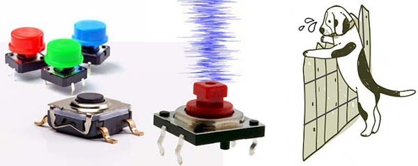
While testing some cheapo crash sensor modules recently, I was quite disappointed with the noisy and dirty output signals they provided. So, I got into the thoughts of restyling hardware debounce circuits suitable for contacts, switches and some other analog sensors that render a transient signal output.
This post shows how to build little circuits to debounce contacts and switches. It includes schematics and quick analysis as well.
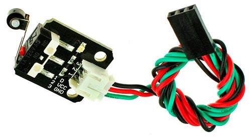
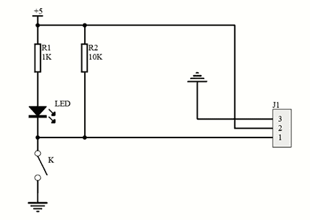
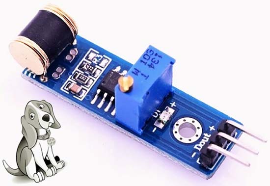
This is an inexpensive crash sensor module that you can find at almost any online storefront. This snap-action switch sensor module, designed primarily for the 3.3V/5V microcontroller applications, integrates a pull-up resistor and a status indicator onboard. Below is the basic schematic of this Chinese module provided by an online retailer at my request.
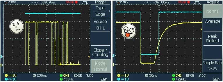
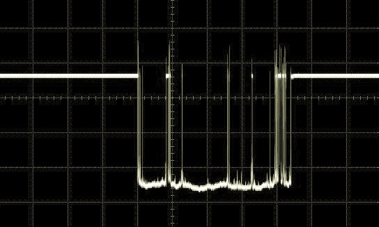
The test was performed by connecting an oscilloscope to the output wire of the crash sensor module powered by a breadboard power supply, and setting the scope to trigger when the switch was pressed. The resultant screen trace with multiple pulses can be seen below.
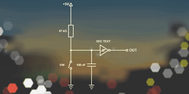
Since the module already has a 10KΩ pullup resistor (R2), I wired a 100nF capacitor in parallel with the switch (K) to make a simple contact debouncer. The resistor capacitor combination then forms an RC network which has a time constant fairly close to 1mS.
When closing the switch, the voltage across the capacitor is discharged through the switch to ground whereas the capacitor is charged via the resistor when the switch is released. As there is very little resistance, the discharge happens quickly but it should take a while to charge back up to the rail voltage, and any spikes caused by contacts bouncing are ingested by the debouncer setup.
It should be noted that upon power-up a brief pulse will be generated from this debouncer because the capacitor needs time to charge up initially. The capacitor is considered to be charged after about 5mS.
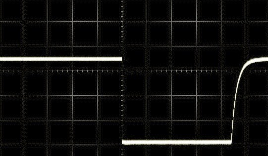
The below scope trace clearly shows an immense improvement in the switching noise. The falling edge shows a clean edge while the leading edge is curved due to the capacitor charging through the resistor.
This idea will work cheerfully in most situations but care must be taken when picking out the RC values to ensure the switching action is fast enough for the proposed project.
Below is a bit enhanced debouncer circuit using one segment of a 7414 hex inverting Schmitt trigger chip. Note that the output is inverted i.e. the output is HIGH when the input is LOW and vice versa. You can also try the CMOS version of the chip – 74C14 (https://www.mouser.com/datasheet/2/308/mm74c14-1193355.pdf) in this circuit.
Besides switch debouncer circuits, sometimes we need pulse shaper/extender circuits when using some analog sensors or modules. The 801 series vibration/shock sensor module is an example because it only outputs a transient signal that is very difficult to use in its raw form. As it seems, almost all Chinese 801S vibration/shock sensor modules are based on the LM393 comparator IC (see below) which does not do anything sensible in this regard. So, I did some research and then a few experiments.
Below is a practical pulse shaper/extender circuit appropriate for use with similar analog sensors and sensor modules (https://www.codrey.com/electronic-circuits/universal-tilt-sensor/). The 4093 quad-NAND gate CMOS IC is used here to keep the output signal stable and well-defined.
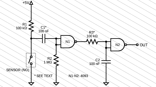
It should be noted that this is a crude design so values of the components, especially C1-R3, need to be sweetened to taste. That is to say that you should tailor the response time depending on your application’s requirement and the feel you would like to give it. A while back, I acquired a set of dedicated hardware debouncer ICs like the MC14490 for some industrial-grade projects. I will share my lessons learned on that too. But that is for another post in the future.
Finally, I admit these ideas are not excellently practical. No doubt someone with better thoughts could bring more pragmatic solutions. So, use a grain of salt when playing with these circuits. Have Fun!