After seeing an inspiring post on a website about making a simple automatic pet feeder using a cheap stepper motor, I decided to re-do some trivial experiments with it. For that I chose the very common Arduino Stepper Motor Kit because it is a good combination of a stepper motor and a driver board.
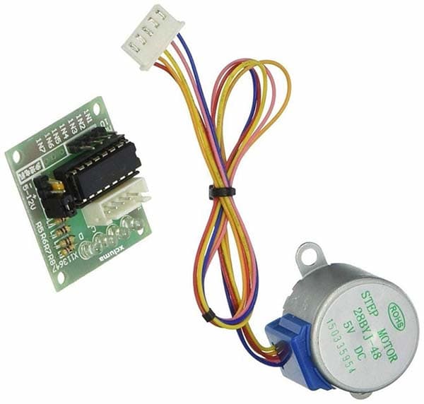
The entry-level kit that most Arduino lovers are familiar with consists of only two things:
- 28BYJ-48 5V Stepper Motor
- ULN2003 Step Motor Driver Board
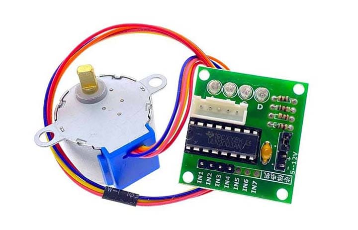
The 28BYJ-48 is a little stepper motor suitable for a large range of practical applications.
Here is its technical specifications (as found in a datasheet):
- Model 28BYJ-48 – 5V
- Rated voltage: 5VDC
- Number of phase: 4
- Speed variation ratio: 1/64
- Stride angle: 5.625° /64
- Frequency: 100Hz
- DC resistance: 50Ω±7%(25℃)
- Idle in-traction frequency: > 600Hz
- Idle out-traction frequency: > 1000Hz
- In-traction torque: >34.3mN.m(120Hz)
- Self-positioning torque: >34.3mN.m
- Friction torque: 600-1200 gf.cm
- Pull in torque: 300 gf.cm
- Insulated resistance: >10MΩ(500V)
- Insulated electricity power: 600VAC/1mA/1s
- Insulation grade: A
- Rise in temperature: <40K(120Hz)
- Noise: <35dB (120Hz, No load, 10cm)
Note that the rated input voltage of the 28BYJ-48 stepper motor demoed here is 5V DC but there is also a 12V DC version with the same model number. Also, it is a unipolar stepper motor, however, a bipolar stepper motor is considered to be at least twice as efficient as a unipolar stepper motor for the same amount of copper on the windings.
The ULN2003 stepper motor driver board provides a direct drive interface between the microcontroller and the stepper motor. It provides 4 inputs for connection to the microcontroller, power supply connector, a motor on/off jumper, a dedicated stepper motor connector, and 4 LEDs to indicate the stepping sequence.
The ULN2003 stepper motor driver board happily accepts a 4-bit command from almost all microcontrollers and in turn applies the requisite drive pulses to step the motor.
Note, the 28BYJ-48 stepper motor takes 4096 steps to rotate its spindle 360°.
The driver board can route 5V to 12V DC to the stepper motor from an external power supply. Make sure the microcontroller’s 5V power supply rail has ample power to drive the stepper motor. However, it is usually a good practice to use an independent 5V DC power source for the driver board (the on/off jumper isolates power to the stepper motor).
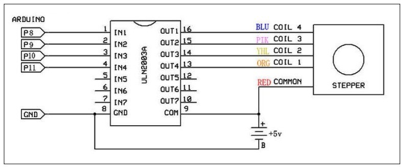
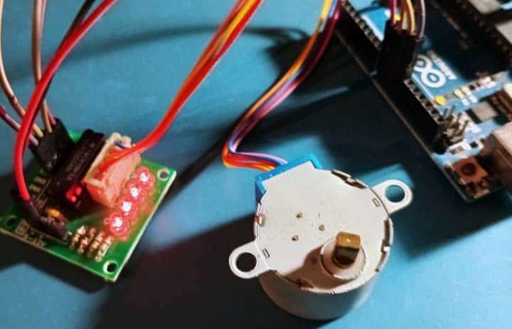
Below figure shows the basic setup to interface 28BYJ-48 unipolar stepper motor to four I/O pins of Arduino thru ULN2003 stepper motor driver board.
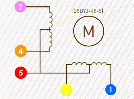
And the 5 leads of the 28BYJ-48 stepper motor:
Now let us see how to drive the 28BYJ-48 stepper motor with the ULN2003 driver board and an Arduino Uno.
In general, the 28BYJ-48 stepper motor comes with a 5-pin connector that fits well in the driver board’s motor connector. The driver board has two pins for the power supply which are labelled (-) and (+5-12V). The board’s (-) pin must be wired to the Arduino’s GND pin. Accordingly, the board’s (+) pin must be linked to the Arduino’s 5V pin. At last, connect the driver board’s IN1-IN2-IN3-IN4 pins to the Arduino board as defined in the Arduino Sketch in use (For example 1N1=D8/IN2=D9/IN3=D10/IN4=D11).
Now see the Arduino Sketch below. Luckily, the Arduino platform has an inbuilt stepper library that allows easy control of the 28BYJ-48 stepper motor with the ULN2003 driver board.
#include <Stepper.h>
const int stepsPerRevolution = 2048;
const int rpm = 12;
Stepper stepper1 = Stepper(stepsPerRevolution, 8, 10, 9, 11);
void setup() {
  stepper1.setSpeed(rpm);
}
void loop() {
  stepper1.step(stepsPerRevolution);
  delay(100);
  stepper1.step(-stepsPerRevolution);
  delay(100);
}
Note at this point that a 5.625° stepper motor has 64 steps/rev. Since the 28BJY-48 stepper motor features a 64:1 gear and 32 steps/rev, to get the final number of steps, the gear ratio must be multiplied by the number of steps per revolution (64×32=2048).
To be more specific, since we run the stepper motor in the full step drive mode*(a method used by the stepper library), each step corresponds to a rotation circa 11.25° according to the datasheet. This corresponds to 32 steps/rev (360°/11.25°=32). In addition, the stepper motor has a specified gear ratio of 64:1, normally it must be multiplied by the 32 steps as pointed above.
*The following are the most common drive modes.
- Wave Drive (1 phase on)
- Full Step Drive (2 phases on)Half Step Drive (1 & 2 phases on)
- Micro-stepping (continuously varying motor currents)
Also, the above code sets the speed to 12 rotations per minute (rpm), the stepper motor should finish a full revolution in about 5 seconds (60s/12=5s). That is, the stepper motor iterates its clockwise rotation for 5 seconds and counterclockwise rotation for 5 seconds.
Well, that is all for now!
A stepper motor can be a good choice whenever a controlled movement is required. It can be used to advantage in applications where it is necessary to control rotation angle, speed, position, and synchronism. One of the most significant feature of a stepper motor is its ability to be accurately controlled in an open loop (no feedback) scheme. Do not miss out on upcoming posts on this topic.