Most modern wireless experimenter kits comes as modules that just plug together rather than individual components. Electronic newbies, practicing engineers, and experienced hands alike are sure to find that these inexpensive modules interesting.
Recently I bought a bunch of ready-to-use WiFi Relay Modules (ESP8266 WiFi 5V 1 Channel Relay Delay Module) from eBay. Here I’d like to share a few secrets of the module, and how you can use it to control your home appliances.
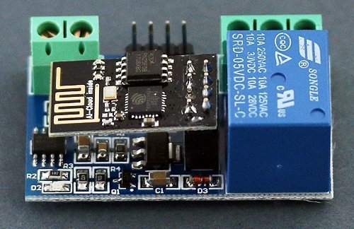
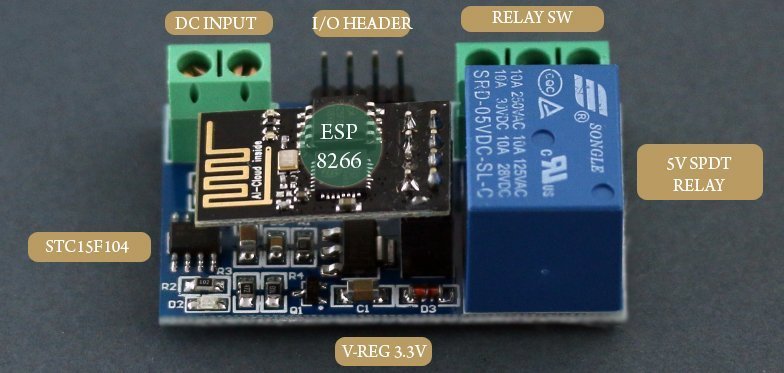
Key component in the base board of the module (designed for 5V dc operation) is a cheap STC15F104 microcontroller. Next important component is a 3.3V regulator (AMS1117-3.3) chip. There’s also a small driver transistor (J3Y) to control the 5V SPDT sugar cube relay. The onboard ESP8266 WiFi module is infact a plug-in type card with an 8-pin header. The onboard 4-pin header works as an I/O header to setup/configure the WiFi Relay Module.
The module can be configured with the help of any “3.3V Level USB to TTL” adapter and a suitedserial debugging software (for instance, USR-TCP232-Test-V1.3). For this, you should connect TXRX-GND pins of the USB to TTL module to RX-TX-GND pins of the 4-pin header. Recommended baud rate is 9600. Also remember to power up the module from an external 5V dc power source.
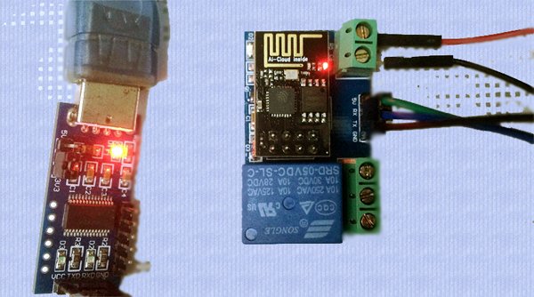
First of all, try to verify basic functionality of the module by using your computer to control the relay directly. Just keep your initial hardware setup intact, but unplug the ESP8266 WiFi card from the module. Next, send serial commands A00101A2 (Relay ON), and A00100A1 (Relay OFF)through the serial debugging software to see the relay actions. Commands must be in hex format, and the baud rate should be 9600.
A noteworthy fact is that the WiFi Relay module supports two modes of WiFi operation – AP and STA (actually one more mode is there – the STA + AP mode). Well, let me switch to the AP (access point) mode.
For AP mode, open the “USR-TCP232-Test-V1.3” Serial Debugging software on the PC to send the flowing commands one by one:
| Command | Description |
|---|---|
| AT+CWMODE=2 | Select AP mode |
| AT+RST | Reset |
| AT+CIPMUX=1 | Open multiple connections |
| AT+CIPSERVER=1,8080 | Configure the TCP server, set the port number |
| AT+CIFSR | Get local IP address, such as APIP, “192.168.4.2" |
| AT+CIOBAUD=9600 | Set Baud rate to 9600 (for older firmware, so if it returns an error, try AT+IPR=9600 instead) |
(& connect with the access point of the WiFi Relay Module on an Android phone – see following pointers)
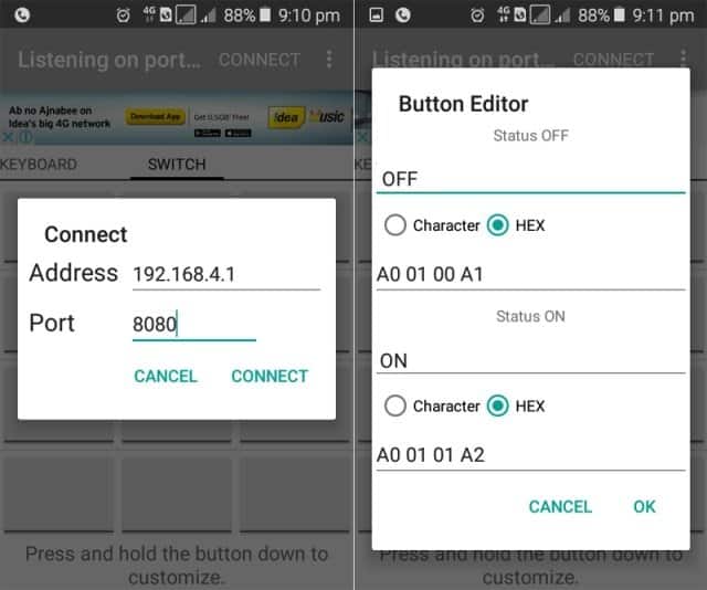
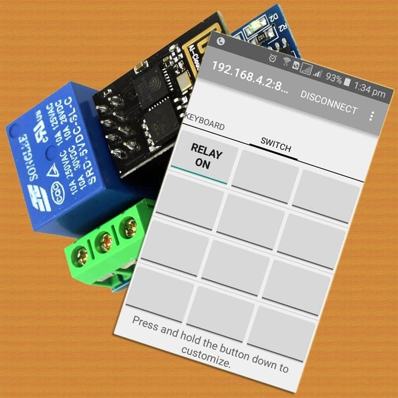
For playing “smart” with AP mode, you need to download and install the “EasyTCP (v4.4)” Android app on your smartphone. Next, open the app, click “Connect” and enter the “IP address” and “Port”. Press and hold a switch button to enter the name and content of the serial command in hex format (A00101A2 relay_on, A00100A1 relay_off). Finally, you can send serial commands from the app for relay control using the pre-configured switch button. Voila!
I’m working hard to prepare the concluding part of this article, and to meet the expectations of my readers/fans. As an ardent reader, if you spot any factual errors, or think I’m casually skipping over important bits, please let me know immediately. Happy Experimenting…

Dear Sir,
Thanks for the job you have done and taking time to publish it.
I have two questions:
– do you have the board datasheet ?
– is the ESP8266 connected to the STC15F104 through UART as I do think so ? Or does STC15F104 use a ESP8266-01 GPIO to manage the relay (and if so what is the ESP8266 pin number)?
Have a very nice day,
Laurent
Hi Laurent, it uses the STC15F104 UART. Intended using it myself as I have run out of available GPIO pins from the ESP12E that I using to control mains voltage heating & light dimming, temperature & humidity monitoring, with an OLED menu display driven by a few up/down/select tactile switches.
Hi Paul – hope you are still working with these. I have just bought one of these board and want to use the esp8266 board to control the relay. Can this be done? I.e. If I send serial commands via the esp8266 programmed via the arduino ide. Something like this:
SoftwareSerial sw(3, 1); // RX=3, TX=1 (D9,D10 or any free pins)
void setup() {
sw.begin(9600);
}
void relayOn() { sw.write((byte[]){0xA0,0x01,0x01,0xA2},4); }
void relayOff() { sw.write((byte[]){0xA0,0x01,0x00,0xA1},4); }