A while back, I got an inquiry via email about building a simple electronics circuit to monitor the status of an analog sensor i.e., whether it is open or working properly. After a little discussion, I designed a very simple circuit for that purpose using readily available and inexpensive electronics components. So, here I am sharing my little thoughts on that design concept.
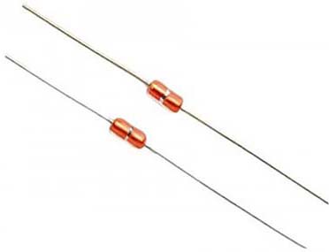
Although the design concept presented here is primarily intended for NTC thermistors, it is also suitable for some other analog sensors such as photoresistors (LDRs). The analog sensor, however, tested here is a special NTC thermistor, often called a glass-sealed/glass diode NTC thermistor. More specifically, a 100KΩ NTC 3950 thermistor in glass encapsulated package. This previous post will show you another simple do it yourself project that uses a bit similar NTC thermistor https://www.codrey.com/electronic-circuits/aquarium-cooler-fan/
Well, let’s start with the basic scheme!
As you are aware, a basic comparator circuit can be used for converting an analog signal input to a digital output. A comparator is commonly used to compare a measurable quantity with a reference or threshold such as two voltages (or currents), and it outputs a digital signal showing the results. The output is HIGH when the voltage on the non-inverting (+) input is greater than the inverting (-) input. The output is LOW when the voltage on the noninverting (+) input is less than the inverting (-) input. So, in this scheme, the LOW output for the fault indicator LED to turn on is obtained when the sensor (thermistor) gets open.
As an aside, while operational amplifiers and comparators may look alike, they’re rather different and tailored to be used in different applications as an operational amplifier (op-amp) may be configured as a comparator but a comparator cannot be used as an op-amp due to its nonlinear output stage!
Anyway, it’s possible to simplify the procedure for tailoring an op-amp as a comparator into two design steps. First, set the threshold voltage/reference voltage. Next, select an op-amp that meets the design demands. For an inverting comparator topology, connect the input signal to the inverting pin of the op-amp and the threshold voltage to the non-inverting pin. A resistor divider together with the supply voltage can then be used to set the threshold voltage (see below).
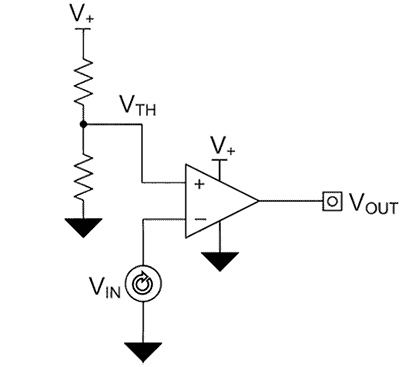
Here, the output (VOUT) of the op-amp changeovers high to the positive supply (V+) when the input signal (VIN) is less than the threshold voltage (VTH) and changeovers low to the negative supply (Gnd/0V) when the input signal is greater than the threshold voltage. An example of when this might be useful is in the case of an analog sensor.
Also note at this point that a modern op-amp usually features a rail-to-rail output, so its maximum positive level is close to the positive supply, and the minimum negative level is close to the negative supply (older designs used structures with headroom of more than 1.5V to both power supply rails).
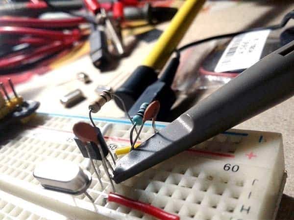
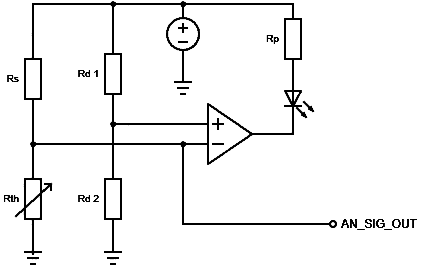
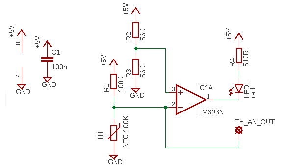
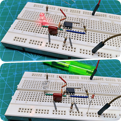
Now let’s get back to the implementation of the improved analog sensor interface concept. Below is its schematic. If the prototype is built on a breadboard, not hard-wiring the circuit components allows easy tweaks later if they are needed for fixes or expansion.
As a quick aside, the Beta Value of a thermistor is an indication of the shape of the curve that represents the relationship between the resistance and the temperature of the thermistor, and it is measured in degrees Kelvin rather than Fahrenheit or Celsius.
Usually, NTC thermistor Beta B value is calculated from measurements at 25°C and 50°C,
that is expressed in B(25/50). For example, “3950 B 25/50 K” indicates a beta constant of 3950 over a temperature range from 25°C to 50°C.
So now you have an unbelievably simple idea to build a better analog sensor interface with sensor failure indicator. Depending on your NTC thermistor value and requirements, you may be able to optimise the implementation by changing the basic scheme. While the design idea shared here is not very much elegant, the experience as a learning exercise is invaluable. Well, it’s about time for another instalment. See you then!
Thanks for the marvellous Application Notes…
- TDK
- Analog Devices
- Texas Instruments
- Vishay BC Components
- Amphenol Advanced Sensors
- Toshiba Electronic Devices & Storage Corporation