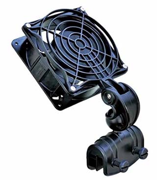
A while back I made a mighty aquarium cooler fan which initially was going to have an Arduino microcontroller to control the automatic cooling system but I moved to a Digispak board when I 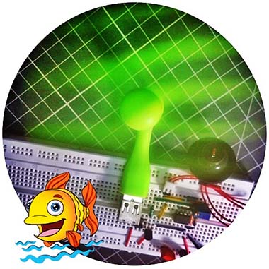 found the build was getting too big. The prototype has worked well for my client over the past few months but now it’s time to build something smaller!
There are several systems available to cool an aquarium and they range from simple to complex. A cheap and cheerful way is to use a fan blowing across the surface of the aquarium water to utilize evaporative cooling to drop the temperature of the tank water. This approach is very simple because the system is relatively cheap and straightforward.
The evaporative cooling method employing a small cooler fan (see above) will work for small to medium fish tanks in effect. First off, note that evaporative cooling is more than just moving heat off the surface of the water. By blowing a fan across the water surface, evaporation is increased and water releases much more energy, and the real magic happens during the water to vapor phase change (recall, evaporating water off your body cools you off swiftly).
Since building the aforesaid microcontroller-based husky aquarium cooler, I’ve wanted to design and build a little poor man’s version centered on a small dc cooling fan possibly available everywhere. I was also planned to employ a simple temperature sensor and fan controller circuitry there, but entirely with discrete electronics components I had laying around.
While I was researching for small and silent dc cooling fans on the web, I came across a budget USB portable fan and thought it would work for my proposed project. The nifty fan has a flexible (gooseneck-form) arm (with a molded USB plug at one end) that allows for the fan to be oriented as desired. Besides, the fan does not have a metal/plastic protection grill which makes it more minuscule and lightweight. My fan has an 87mm fan diameter, and around 145mm arm length (from the end of the USB plug to the end of the fan canopy). The maximum current consumption of my nifty USB fan is about 300mA at 5V.
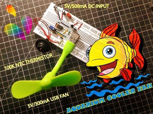
Naturally, I went for a quick build after the purchase. The new design is nothing but a temperature-controlled aquarium cooler fan based on a 100K NTC thermistor and tailored to run by any common USB power bank or travel charger.
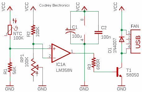
Following is the circuit diagram (v1) of the aquarium cooler fan. I rigged up and tested the circuit out with one-half of the LM358N dual op-amp, and a glass diode 100K NTC thermistor. Since it’s clear that the easiest solution to drive my USB fan will be a transistor switch, I used the cheap S8050 n-p-n transistor at the output of the LM358 op-amp. The maximum current demand of the USB fan in this circuit (as observed) is around 250mA, and the S8050 transistor can handle that drag gently.
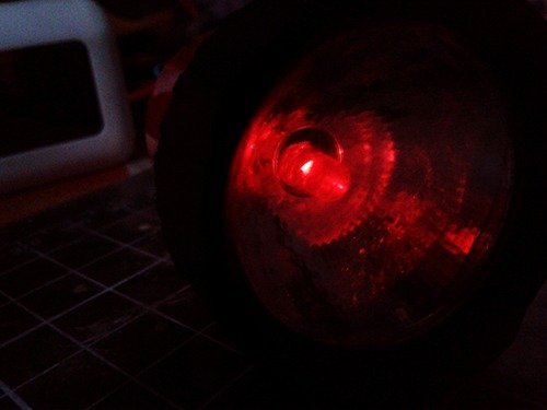
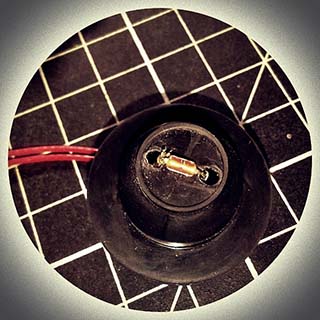
As you can clearly see, a ‘special’ glass diode thermistor is used here intentionally, rather than going for an everyday NTC thermistor. The NTC thermistor is a temperature-sensitive resistor. Depending on the temperature, the value of resistance will change. By reading the value of this resistance, we can determine the temperature. There are several different kinds of temperature sensors, but this particular one is generally used in rice cookers, induction stoves, and cooktops. The glass diode thermistor consists of a range of NTC chip thermistors, usually in 10K-100K range, in DO-35 style glass package (diode outline) with axial solder-coated copper-clad steel wires. The glass body provides a hermetic seal and voltage insulation and excellent stability. Simply google “100K induction heat sensor diode” to get one for this project.
Needless to say, the thermistor (NTC 100K) is really the heart of this circuit. At ambient temperature (25°C), the thermistor has a resistance of about 100KΩ. As the thermistor heats up, its resistance decreases until the voltage threshold determined by the 100K trimpot (RP1) is reached. At this time the output of the LM358 op-amp (IC1) goes from low to high (~3.4-3.6V) causing the S8050 transistor (T1) to be saturated and allowing current to flow through the USB fan. Since the fan driver transistor is wired as a low-side switch, do not omit components D1-C2-C1 in this circuit. Further, you may need to add an additional electrolytic capacitor (100uF to 470uF) across the terminals (1 and 4) of the USB fan connector as it might help to suppress the fan noise as well as providing a capacitive start for the fan motor.
Experience has shown that lazy soldering can damage (or alter the characteristics) of the glass diode thermistor. Luckily, the device comes with Butt type crimp connectors, short-length heat-proof wires, and a pre-coupled 2-pin connector. Pretty great!
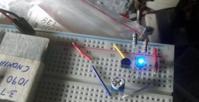
Here’s what the whole works looks like when it’s all hooked up on the breadboard:
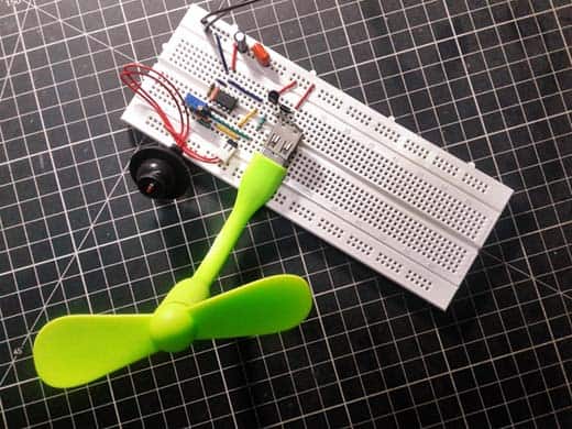
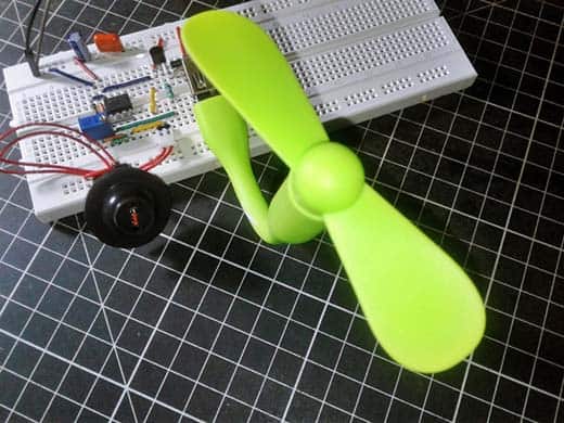
The whole circuit can be constructed on a piece of dot or strip protoboard. After successful construction and pre-flight test, enclose the controller electronics (excluding the thermistor) inside a waterproof plastic can or tin. It’s important that the thermistor is sited so that the fan does have a chance to cool that area down. By the same token, don’t put the thermistor directly in the aquarium water. Experiment to find the best sweet spot(s).
Apparently, you can use any other 5V dc motor cooling fan (even high current ones) in this design perhaps after replacing the fan driver transistor (and its base resistor) with an appropriate one (also consider a heathy USB power supply). Anyway, the setup is fairly easy with the USB fan touched on – just place off it to one side of the fish tank, and then orient it aright. The flex arm works well to let you angle the USB fan down slightly to direct the air right at the opening. Finally, plug the USB fan into the USB connector of the enclosed controller circuitry, and you are set. For an open-tank mini aquarium, the entire setup would be ridiculously easy as you simply need to get airflow on any part of the water.
Quite often, in a planted or marine aquarium, much heat is transferred into the water from the associated aquarium lights as well. This results in quite a bit higher temperature than the recommended range of 25ºC to 28ºC. The fish and shrimp can probably survive with the temperature swings, but causing this daily would lead to some mishaps, I felt. So, take enough time to finetune the trimpot right in your prototype.
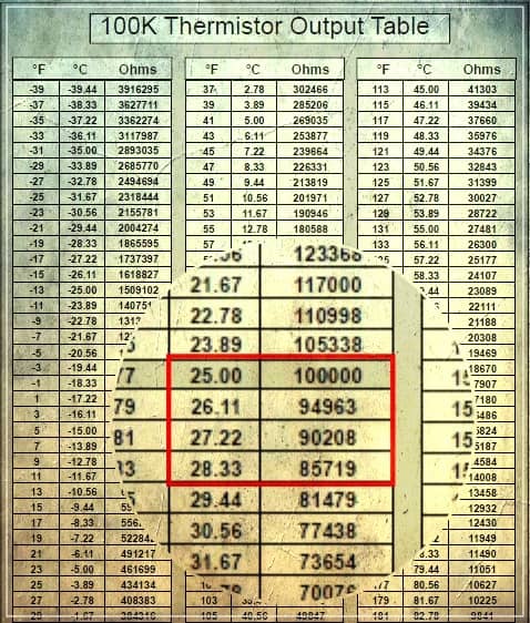
Although the recommended value of reference resistor (R1) for the thermistor used in this circuit is 100KΩ at 25ºC, I used a bit lower value one (56KΩ) empirically just to ‘speed up’ the overtemperature detection in my own way. It’s important to note that a thermistor’s change in resistance is non-linear, and it follows a pre-defined curve which is provided by the thermistor manufacturer. Below you can see a snip of the thermistor output table copied from the datasheet of my 100K NTC glass diode thermistor.
Finally, this type of temperature-controlled aquarium cooler fan design isn’t very suitable for hefty display case marine aquariums. In those situations, the controller electronics should have proportional, integrative, and derivative (PID) parameters. Albeit, for minuscule home aquariums, this crude idea serves us well!