Everyone knows about the anti-sleep alarms that can keep us awake while we’re driving. There are two types of anti-sleep alarms – the first (and costly) type of alarm is built right into the vehicle to discern a driver’s fatigue and correct the problem accordingly, whereas the second type fits over the driver’s ear and sounds an alert when the driver/wearer starts to fall asleep. The latter, the over-the-ear alarm, is extremely cheap and readily available. Even a simple Google search for “Nap Zapper Alarms” will show you a myriad of catnap killer gizmos under different brand names usually coming out of China (see the lead image). Although sounds funny, such a wearable little device might be a needy one for drowsy drivers, students, and certain laborers. You can find them for $10 to $50, buy don’t buy!
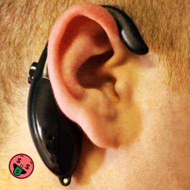
As you can see, the lightweight and dirt-cheap plastic gizmo has an arm that slips over one ear. When it’s powered up, while the wearer is looking straight ahead, nothing will happen in that standby state. However, when the user’s head tends to fall forward as he/she doze off, a tilt sensor located inside the device detects that tilt from 0°to, say 15° or 30°angle, and fires a piezo-sounder to deliver an ear-splitting alert loud enough to wake up the wearer. Nice concept, eh? But sadly, often you can find a $1 (or less) electronics assembly inside a bogus $10-$50 nap zapper alarm!
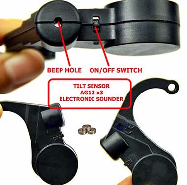
The electronics assembly is nothing but a tilt-triggered electronic sounder powered by three AG13 button cells wired in series (4.5V). In some devices, the sounder is just a small active piezo-buzzer, but some other models (luckily) have an alarm COB (chip on board) to drive a tiny piezo-speaker. The tilt detector in one model that I randomly picked is a ‘gimmick’ tilt switch.
At this point I have no plan to post an in-depth teardown note (sorry), instead, I’m going to share my quick thought on making another decent nap zapper alarm by utilizing a few stock components. Okay, let’s build the merest version with some discrete electronics parts.
Now to the components list:
- T1: S8050
- T2: S8550
- R1: 270K ¼ w
- R2: 100Ω ¼ w
- C1: 100uF/16v electrolytic
- C2: 10nF polyester/ceramic
- LS1: 16Ω Piezo-Speaker (see notes)
- TILT SWITCH: Roll Ball Switch (Example: SW-520D)
- BAT: 1S LiPo (3.7V/150mA minimum)
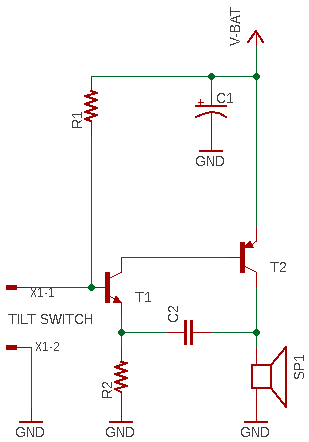
The design shown above is based on a textbook circuit (so don’t give me credit for this work) in which a complementary (PNP and NPN) BJT-pair is wired as a high-efficiency audio-frequency (AF) oscillator, directly driving a small piezo-speaker (the so-called computer motherboard beep speaker). The tilt switch can be any type, however, pay close attention to its orientation in the final circuit board/enclosure so that its contacts rest in the closed state (on) during idle (0°) condition, and gets opened inactive state (off) i.e. only when there’s a sensible tilt (> 20° or so). Look below to get a practical orientation pointer.

Check out the following links to see some of my tilt switch sensor projects:
Universal Tilt Sensor
Magic Cup Light Module – Quick Tries
Arduino Tilt Sensor Experiment
Midget Tilt Sensor Module
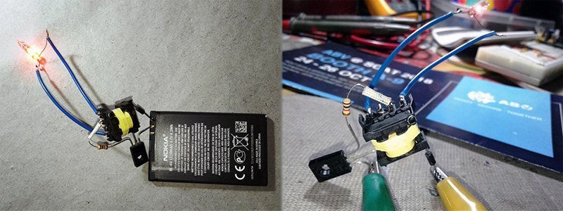
This circuit doesn’t have a power on/off switch. It’s not all-important as the current consumption is negligible in idle state. The circuit will work from a dc voltage of 3V, and hence a very small (~150mA) 1S LiPo battery (3.7V) is the best candidate here. The entire circuit constructed on a small Veroboard can finally be placed inside a little handmade or 3D-printed lightweight enclosure. This is how it should look when completed if I can afford to spend some hours with the 3D printer!

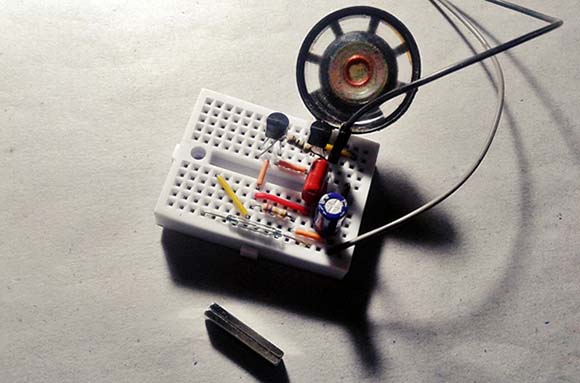
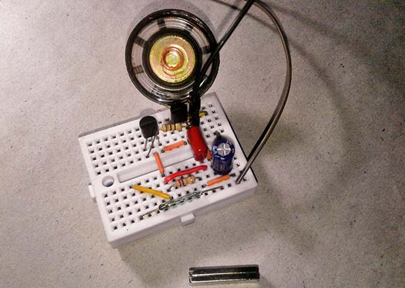
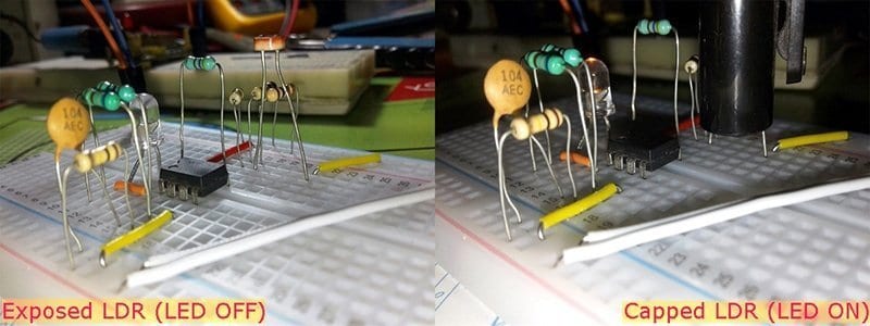
I successfully tested the breadboard prototype, at first with my trusty 16Ω mylar speaker and a reed switch in place of the purposed sounder and sensor. While running with a 10nF (0.01uF) capacitor as C2, the measured output tone frequency is around 660Hz. Below you can see my quick breadboard assembly.
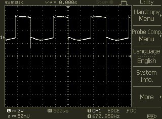
And, a random oscillogram was taken while the oscilloscope was lazily probed across the 16Ω loudspeaker (take note of the terrific crest).
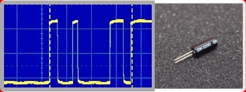
Now you know how I tackled together a little nap zapper alarm using junk box components. Looks good? Although touched on before, I’d like to say a bit more about the tilt switch that’s being used here. The SW-520D is a ball tilt switch sensor rated for a maximum current of 30mA at 20VDC. As you might be noticed, the presented circuit is configured in a way that the alarm will wake up only when the tilt switch is in off (break) state. That’s done intentionally to get rid of the possible contact bouncing occurs when the tilt switch shifts to its on (make) state. Otherwise, the design will demand a few more components to provide a switch debounce mechanism. The inherent switch bouncing effect might last up to 60 -70mS (see below waveform).
Finally, I was able to get hold of a pretty good design idea for the first version of my microcontroller-based nap zap alarm. I will post up full details of that feature-rich, very loud, and extremely compact anti-sleep device here later. I was somewhat reluctant to build it but was encourage to do so 😊

Update: This is not a link that generates any kickbacks or credits, I include it here for those who are interested!
You may checkout this link to get a compatible piezo-speaker for this project
https://www.amazon.in/SUGOITM-Speaker-Interanal-Computer-Motherboard/dp/B085BN8Z1Q