Lighting is very essential in the wake of a disaster! When a disaster depletes your utilities buries everything in darkness, being capable to enlighten your environs can be a matter of survival 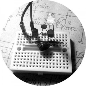 counting on your own destiny. Equally, when night falls a refugee camp is in darkness and it can be dangerous for refugees to do even the most routine of activities like walking to the bathroom or going to take something from outdoors in moonless nights, particularly for women and girls who are exposed to a substantial risk of sexual violence. Let me recite, young females, are among the most vulnerable in refugee camps, and need extra care to withstand the harsh conditions of the refugee camps!
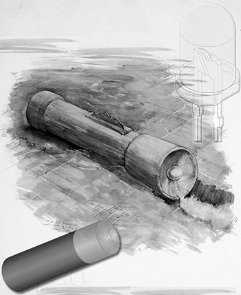
For stationary and/or portable lighting where a minimal light and elongated burn time is called for, consider making and using this little rescue light which is nothing but a single cell-powered single LED flashlight, a good to have a device on hand as a backup plan.
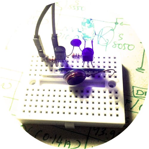
This article shares my thoughts on the construction of a small electronic rescue light intended for the most vulnerable communities simply to bestow enough light and security in the darkness, giving them a feel of self-worth, comfort, and protection after dark. To keep the running cost down and the ‘fueling’ task lenient, the staple design is configured to work with a standard single-cell AA battery (non-rechargeable 1.5V or rechargeable 1.2V). Moreover, this is an adaptative design that lets you experiment with a number of fabulous ideas. However, it’s important to keep in mind that an adaptive design requires a lot more effort early on but has the potential to reduce overall costs further down the road. Well, let’s start by understanding the basic schematic (v1) of the simple rescue light.
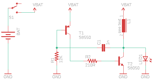
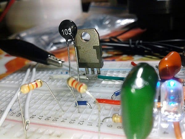
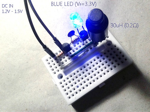
This basic circuit shown above is in fact a revised replica of one good old circuit from the year 1987! This is a simple two transistor PNP-NPN type voltage boost circuit that seems to work very well at 1.2V to 1.5V DC input and I got better results with high-efficiency 5mm blue and white LEDs. I decided to use this basic circuit as a test circuit to try the different inductors lying around, and started my first test with a 30uH (0.2Ω) 500mA power inductor. I started with a standard 1.5V penlight cell (AA) but I found that a 1.2V rechargeable type also worked with no difficulties.
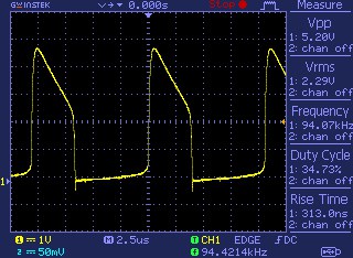
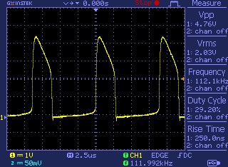
During testing it’s found that the input voltage is boosted nicely from 1.5V to circa 5.2V peak to the peak output voltage and it’s a rough 94 kHz square wave with a 34% duty cycle. I powered it also with my adjustable digital lab power supply to see how it responded as the input voltage was lowered and it continued to put out reduced light down to 0.7V input without a problem.
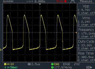
As you can see in the next scope capture shown below, with the 1.2V input, the boost circuit played well as before however the frequency is increased a bit (112kHz, 29% duty cycle), and the output voltage is about 4.8V peak to peak. The observed total current consumption is 120mA at 1.5V input and 90mA at 1.2V input.
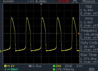
Later I made some tests with another inductor as well because I got a small 10uH (0.18Ω) SMD inductor from a defunct Chinese power supply module.
The winding is on a small ferrite core and has two metal legs soldered to the solder pads on the circuit board. So, I had to extend the leads to connect it to my breadboard setup. The total current consumption of the setup is about 140mA and 120mA at an input of 1.5V and 1.2V respectively. See the random oscillograms provided below to get an idea of the output voltage, frequency, and duty cycle shifts.
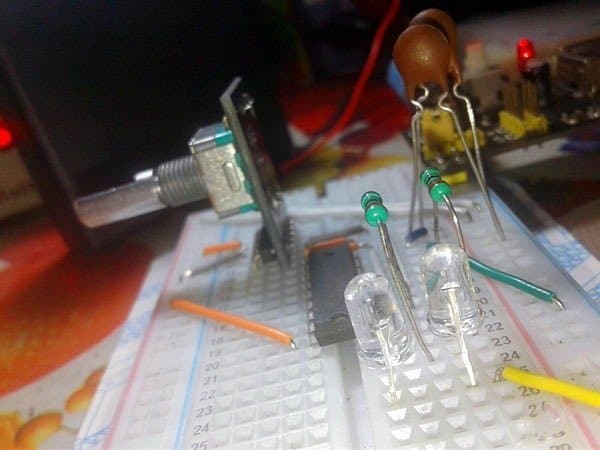
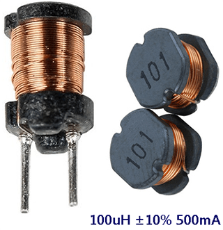
My other thought for an alternative inductor for this circuit came to me because I doubt that my primitive design might need a ‘better’ inductor part. If you are satisfied with the light intensity generated by the white/blue LED all you need is the above-described circuit. If not, then simply replace the 10-30uH inductor with a 100uH ‘readymade’ power inductor (see below). Perhaps, then the setup is able to drive a 1W white/blue or more LED with a 1.2V-1.5V cell, to where it will put out at least a ½ W, but somewhat changeable by the maker.
Another thing that you might want to look at is trying different value components in place of or in addition to the presently existing passive components R1-R2-C1(do your homework aright) though keeping the transistors T1-T2 intact. I’m pretty sure with some clever tweaking, the initial design would be able to deliver a much better performance.
The neat thing about this design is that it has the bare minimum number of components to do the job. Yes, now you’ve an adaptable rescue light design with a few parts to yield a compact voltage booster that can provide sufficient output to drive white/blue LEDs. If you aren’t making this as a commercial product, you have a scope for freedom in the selection of the key components. Anyway, keep note that nearly every inductor parameter affects the performance of this circuit.
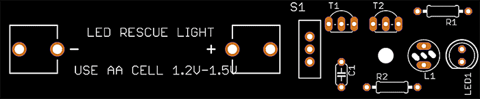
Once I had the breadboard version working, I thought about the design of a small customized printed circuit board as I really wanted this rescue light to be a nice everyday carry. But you don’t need such a PCB to build your rescue light. It’s easy enough with a flake of common stripboard!
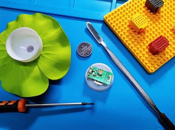
Further, while I was doing a Google search, I chanced upon one cunning template for a 3D-printable pocket flashlight enclosure. Could I fit my ‘dreamed up’ circuit board in there and the battery besides? Only one way to find out – let’s see!
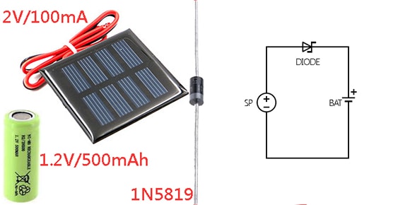
This simple idea can be modified farther as a solar chargeable rescue light by adding a small (2V/100mA) solar panel and a rechargeable battery (1.2V/500mAh Ni-MH). With this, most design goals have been met.
Finally, good luck with the project and let me know if I can help!