There is various electronic test equipment for testing electronic components and find out problems in electronic circuits. But before going to know about the list of electrical test equipment. Let’s know, what is debugging? and What do you mean by the bug?
A bug means an error or flaw. Debugging is a process of finding and resolving errors or issues. It is a technique that helps to test and remove errors in our program or hardware design.
How to Debug Electronic Circuits?
In Electronics, it is important to do debug or test the circuit once the design is completed. It helps to identify the failures or flaws which can prevent the circuit from damaging. Debugging is a skill as useful to every electronics engineer.
How does it help to prevent failures? When you are designing a circuit, your design might work or might not. If it is working, fine. If it is not working, you need to debug (fault or issues) and resolve the error in the circuit.
While designing a circuit, there are possibilities of many issues. So, it is important to test when the circuit has issues. Otherwise, the circuit would behave oddly and the circuit may go wrong. Moreover, there may be issues with the assembly, wiring the circuit or components. If the assembly or wiring is the issue, it is easy to check with the circuit schematic and debug.
But with the components or with the complex circuits in hand, it will be complicated to understand the behavior of the circuits. With the debugging tools in hand, we can probably go down and analyze what’s happening in the circuits.
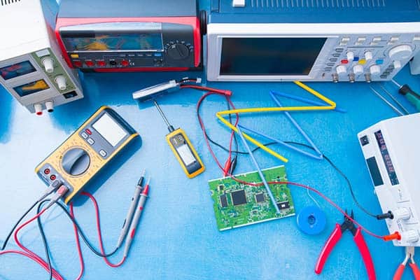
You will have to analyze and test the circuits to know what’s going on there and it can be easily tested. There is some best electrical testing equipment used in electronics to check the electronic circuits, to measure the voltage and current, to generate and view the electric signals. They are:
- Multimeter,
- Oscilloscopes,
- Function Generators,
and some more specialized tools such as:
- Spectrum Analyzer,
- Logic Analyzer,
- Frequency Counter, Etc.
The electronic test equipment is often used to test, verify, and troubleshoot issues in PCB, analog, and digital hardware circuits. A few common things to consider for testing the hardware:
- Input & output – Voltage and Current of the circuit
- To verify the component value
- Track the PCB continuation or check for Short-circuited portion
- Check Oscillator signal/ Noise
- Sensor & amplifier signal
- Op-amp problems/IC issues
- If the component is working
- Polarity check
- Logic circuits
- Bus signals
- Verifying audio signals
Types of Electronic Test Equipment
Here are some of the popular electronics equipment for testing electronic hardware circuits. Each test equipment has its function, operation procedure, and application.
Digital Multimeter
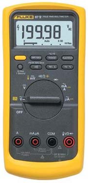
A Digital multimeter (Fluke) is a tool used for measuring, troubleshooting, and testing various electrical circuits and parameters like AC/DC voltage & current, resistance, transistors, diodes. It is the most helpful tool in debugging electronic circuits.
The following are some of the applications of testing using a digital multimeter:
- Continuity test can be done using continuity mode. It helps us to trace the PCB and find if the circuit path has continuity.
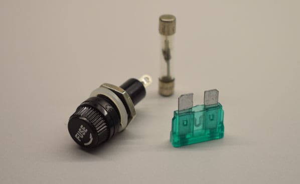
- It can be used to test fuses, switch contacts, and electrical connections.
- Transistors and diode can be tested by using diode mode.
- The power supply output voltage can be checked.
- Potentiometer resistance output can be checked using resistance mode.
Digital Oscilloscope
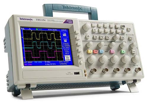
A Digital oscilloscope is often called a scope which is an essential and primary tool in electronics. It can depict signals visually in a graphical format that plots X-axis and Y-axis as voltage and time respectively. It helps to measure, analyze, and troubleshoot the circuits using the signals.
An oscilloscope lets you verify and troubleshoot:
- Power supplies
- Op-amp output & sensor output
- Voltage and frequency of audio input signals & various output signals
- Serial bus and automotive bus signals to see if we are getting the actual data that we are sending and receiving
- Noise can be seen in amplifiers, transmission lines, wave propagation. It can be tracked down using an oscilloscope and can be resolved
Function Generator
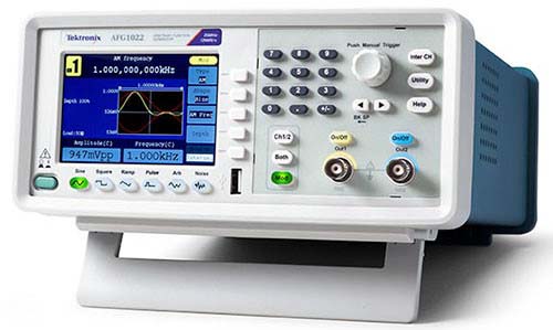
A function generator which can generate different waveforms such as sine wave, square wave, triangular wave, sawtooth wave, ramp, and pulses. It can be used with the oscilloscope to test and troubleshoot electronic devices and circuits.
To verify the cut-off frequency while designing the op-amp filters, a function generator can be used to vary the input frequency and oscilloscope can be used to view the output signals.
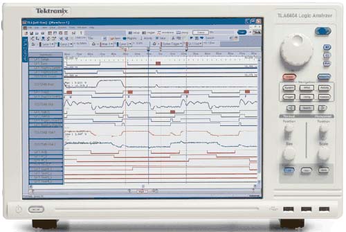
Logic Analyzer
Spectrum Analyzer
A Spectrum Analyzer is used to measure the amplitude of an input signal versus frequency. The difference between the oscilloscope and spectrum analyzer is that an oscilloscope shows how the signal changes over time and the spectrum analyzer shows how the signal changes with respect to a different frequency. The primary use is to measure the power of the spectrum of known and unknown signals.
Spectrum analyzer is used to test:
- Electromagnetic interference problems- to identify the source of RF emissions and to resolve it.
- To troubleshoot radio frequency signals.
Frequency Counter
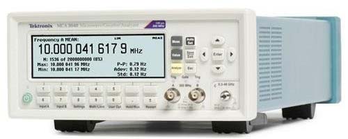
The frequency counter equipment is better than the microwave analyzers. The reason is, the frequency generator offers better resolution and records the negligible frequencies with ease. Moreover, it measures phase, time, and signal power.
The frequency counter is used for:
- Capturing small frequency signals.
- Time measurement
- Frequency ratio measurement
- RPM measurement
Network Analyzer
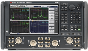
Vector Network analyzer equipment measures the impedance of devices like an antenna, RF cables, Connectors, etc. The analyzer finds out the VSWR and radiation pattern of antennas. Moreover, it detects the interference in the cables and electronic components.
The applications of network analyzer are:
- Tuning the antennas.
- Testing the signal loss in RF cables, GPS antennas, GSM antennas.
- To find out radiation patterns for different types of antenna.
- Linear and nonlinear components characterization
- Signal measurement, LF, and RF components testing.
- PCB manufacturing test.
RF Power Meter (Wattmeter)
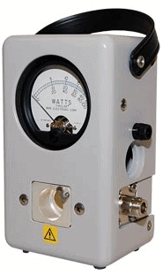
The RF power meter or Wattmeter measures the RF signal in transmission lines. It is used in FM, AM, and CW modulation applications. The reading is shown in watts for different powers and frequencies.
The RF Wattmeter is used to measure:
- RF power in 50-ohm transmission lines.
- To know the power level in watts.
Conclusion
While designing a circuit, debugging is also a part of it. We can’t just design a hardware circuit and manufacture thousands of electronic products without verifying it. The circuit problems need to be found and resolved to run a good working circuit.
To make debugging easy, there are different types of electrical and electronic test equipment like microwave generator, digital pattern generator, arbitrary waveform generator, etc., in electronics to detect faults and make sure the hardware works fine.