While working on big Arduino projects, quite often you might find that even stacks of the I/O pins run out rapidly as the design concept gets more complex! This is especially true when you want to read several buttons because each button calls for a devoted pin of Arduino to read its digital states. Therefore, it’d be a clever idea if you could use less pins, wiring various buttons to a single input pin, for instance. But how it’s possible?
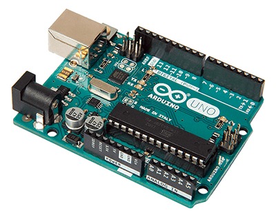
Luckily, the quite popular Arduino Uno board has 12 available digital I/O pins (D2-D13) and 6 analog input pins (A0-A5), and naturally the digital I/O pins get occupied faster than the analog input pins. Okay, then what about using multiple buttons on one analog input pin? Let’s see how it works!
The analogRead([pin]) function reads the analog voltage value present in an analog input pin. Note that unlike the digital value (LOW/0 or HIGH/5V), an analog voltage can have any value between 0 and 5V. This way, the function will map the voltage value from 0 to 5V to integer values between 0 and 1023. A bit complicated, but even a novice can understand it better by reading the rest of this article.
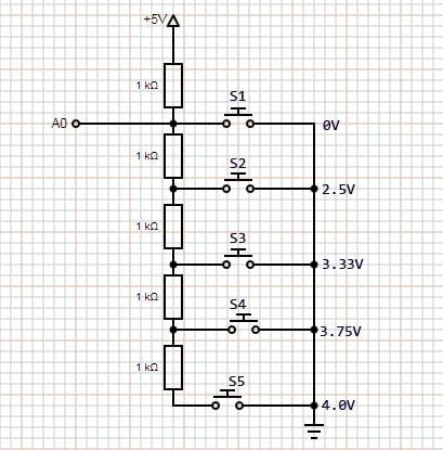
Well, let me start with a nice simple solution. A resistor ladder is a clever but hyper-simple way to attach multiple buttons to an analog pin (more technically, analog to digital converter pin or ADC pin) on an Arduino. Actually here we’re creating a variable voltage divider. If you measure (or calculate) the values read by the analog input pin, you can interpret each reading as a different button being pressed with a little code. Briefly, at first, you have to connect the buttons like this, upload the given code to the Arduino board, and then you can play with the buttons to ‘see’ them in your serial monitor!
#define BUTTON_PIN A0
void setup() {
Serial.begin(9600);
pinMode(BUTTON_PIN, INPUT);
}
void loop() {
int result = readAnalogKey();
Serial.println(result);
}
int readAnalogKey() {
int button = analogRead(BUTTON_PIN);
if (button > 921) return 0;
if (button < 256) return 1;
if (button < 598) return 2;
if (button < 726) return 3;
if (button < 794) return 4;
if (button < 921) return 5;
}
As you might have already observed, rather than telling the Arduino sketch to look for the accurate values we gestating the analog pin to read, here we set a range of values that can be interpreted as belonging to a particular button status, by calculating the points halfway between each expected analog reading and set these as the boundaries of our ranges. Assuming tight-tolerance 1K resistors, the voltage readings for each button should be around 0.0V, 2.5V, 3.33V, 3.75V, and 4.0V, equating approximate analog readings of 0, 512, 683,768 and 819.
To be frank, this cunning idea, I shamelessly took over from the web, might work for a little number of buttons if we measure each value, calculate and hard-code our ADC boundaries for each button. But magic numbers are tough (https://stackoverflow.com/questions/47882/what-is-a-magic-number-and-why-is-it-bad) – we will look just how far we can tweak this for the better in a future article. Now let’s move to a more sensible practical solution!
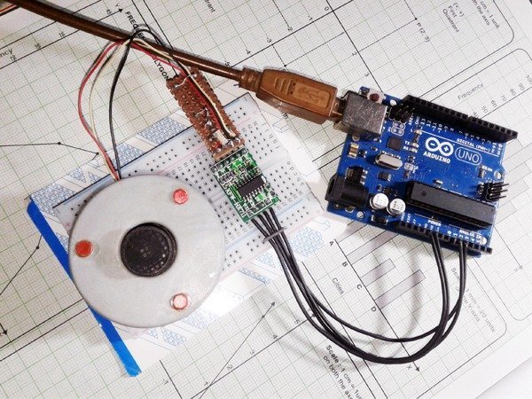
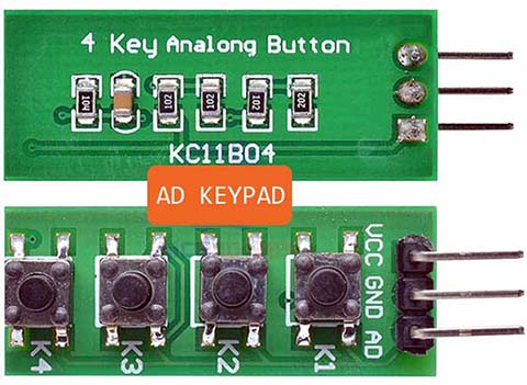
This is the photograph of a readymade 4-button analog keypad (AD Keypad) hails from China. Recently I got a few from https://www.aliexpress.com/i/33032529637.html
Now we know that an analog keypad renders a different voltage (or analog value) depending on which key is pressed. This can be read by a single analog pin on the Arduino. And, it’s fairly straight forward to build our own – just wire the buttons in the same way as a conventional potential divider. Coming after is an easy do it yourself analog keypad button tester set up with an LCD screen to show the outcome.
With the below Arduino Sketch, the 10-bit ADC of Arduino Uno will return a numerical value between 0 and 1023 in an LCD screen which relates to an analog voltage being read of between 0 and 5VDC. Remember, keeping all the resistors at the same value gives you a pretty fair spread between the values, however, the values can drift slightly due to the tolerance of the resistors used and parasitic resistance introduced in the circuitry!
#include <LiquidCrystal.h>
LiquidCrystal lcd(8, 9, 4, 5, 6, 7); // 16x2 LCD Interface
int a = 0;
void setup()
{
  //pinMode(A1, INPUT_PULLUP); // External Analog Keypad to A1 (20K-50K Pull-Up*)
  lcd.begin(16, 2);
  lcd.print("---BUTTONTEST---");
  delay(2000);
  lcd.clear();


}
void loop()
{
  a = analogRead(1);
  lcd.clear();
  lcd.setCursor(0, 0);
  lcd.print(" analogRead() ");
  lcd.setCursor(0, 1);
  lcd.print(" value is :");
  lcd.print(a);
  delay(1000);
}
On a side note, the internal pull-up option of A1 is not called this time because the internal pull-up isn’t a real resistor, isn’t linear, and is only specified to be between 20K and 50K. While we’re taking something with an analog input pin, it’d be better to use an external resistor of known value.
Thus after making the button test setup, you should determine the values for each button input, and then have your code look at a range of values when reading the analog pin A1. Note that I used (a fake copy of) the DFR LCD Keypad Shield (v1.0) just to speed up my build process, and wired the analog keypad output to its A1 input, leaving the onboard button keys (hard-wired to A0) of the shield. Nevertheless, you can use any compatible 16×2 LCD with the Arduino Uno, the shield is not very essential. This schematic is devised for you!
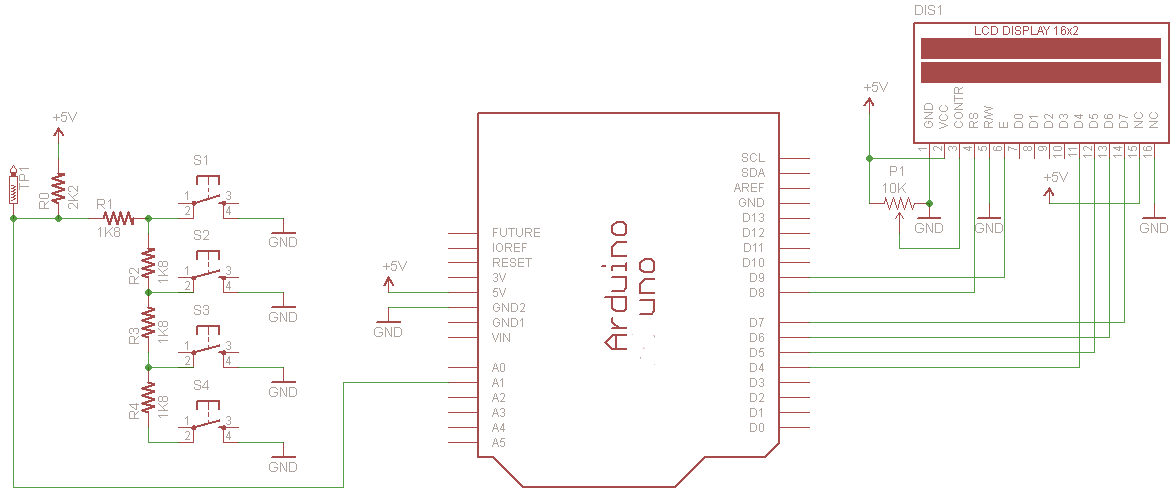
Inclusion of the 2K2 pull-up resistor (R0) on the analog pin (A1) means it’s putting +5V(actually a bit lower) on the pin which means when no button is pressed i.e. in a standby state, A1 reads about 1023. I repeat, due to inherent tolerances in the components you are very likely to get slightly different values.
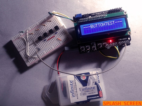
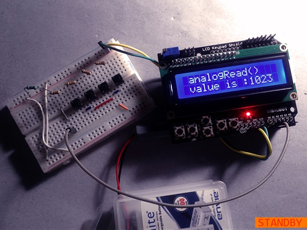
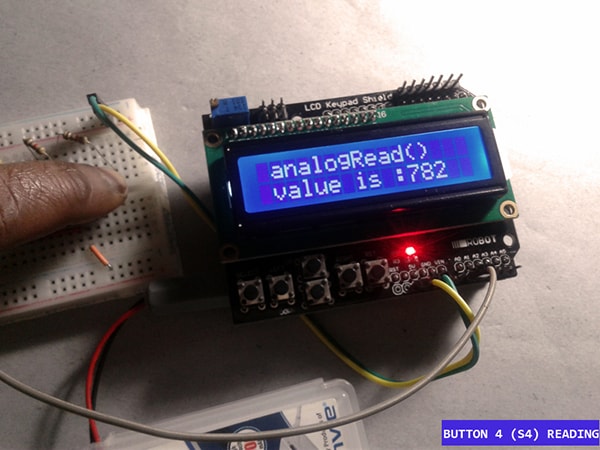
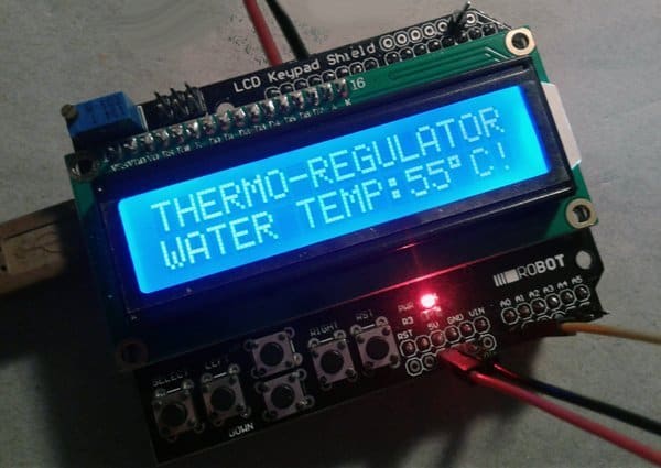
In my analog keypad button tester prototype, LCD shows the following approximative values:
- No button = 1023
- Button S1 = 458
- Button S2 = 632
- Button S3 = 725
- Button S4 = 782
Great! Now you know how to create a simple user interface with multiple buttons that allow various voltages to be read by a single analog pin of the microcontroller. Since each voltage read would cause analogRead() to return a particular value, you can use it to trigger a specific action. What about a motor horn reacts to various button presses, or an alert lamp responds to different key entries? It’s an easy task as you simply need to find out the values for each button in your analog keypad, and then have your code look at a range of values when reading that analog pin. The values will always drift counting the available voltage (and temperature be around). This is normal, therefore it’s a good idea to use a range of values for each button rather than a single value.
Credits & References