 More and more homeowners realize the advantage of having an automatic driveway light. An automatic driveway light is very convenient and an excellent way to save electricity. Now it’s easy to automate an already existing manual driveway light. You can build this affordable automatic driveway light controller yourself using off-the-shelf electronics parts.
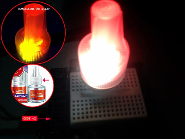
The electronics for this inspired project are very simple. I used a small circuit to monitor the state of a switch/sensor. When the switch/sensor is activated, the circuit will wake up and switch the driveway light(s) on for a finite time. The minuscule electronics circuitry is intentionally chosen largely due to its convenient ability to be housed inside a little enclosure.
Digispark ATtiny85 Hardware
I’ve used ATtiny85 microcontrollers both for amateur and professional projects. These tiny microcontrollers ran the code I programmed them with, but once the final device was ready, it was hard to change the firmware as the end-user needed an external programmer and the software tools to update the firmware. Often, a more convenient solution is to use a Digispark board (http://digistump.com/products/1). So once again I’m using my favorite tiny microcontroller board – the Digispark – for the above-mentioned reasons. Below is the schematic of the automatic driveway light controller designed using the Digispark Attiny85 microcontroller development board.
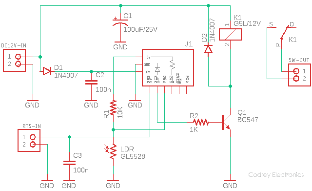
Referring to the above schematic, the first 2-pin JST connector is the power connector for inputting 12VDC from an external power supply, while the next 2-pin JST connector is the trigger input to accept a switching signal from an appropriate external switch/sensor. The third 2-pin JST connector is linked with the switching contacts (C & NO) of the electromagnetic relay (K1). You could use this connector to switch your driveway light(s).
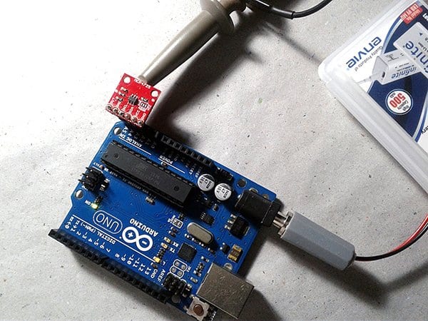
The 5mm photoresistor (GL5528 LDR) in this circuit is to ensure that the driveway lights are switched only at night time, or only when there’s not enough ambient light on the driveway.
Digispark Attiny85/Arduino Code
This is the Arduino-style code for Digispark. The bootloader that’s pre-programmed on the Digispark allows it to act as a USB device so that it can be programmed by the Arduino IDE (https://digistump.com/wiki/digispark/tutorials/connecting).
/*
 * Project: Automatic Driveway Light Controller
 * Version: v1.0/Digispark ATtiny85
 * Author: T.K.Hareendran/03-2021
 * Note: Read the full article before you start your project!
 */

#define LAMP 1 //P1
#define SEN 0  //P0

void setup()
{
  pinMode(LAMP, OUTPUT); //Set P1 as Output
  pinMode(SEN,INPUT_PULLUP); //Internal Pull-Up
}

void loop()
{


  int value_LDR = analogRead(1); //Read P2
  int value_SEN = digitalRead(SEN); //Read P0


 if((value_LDR >600) && (value_SEN==LOW) ){ //Trigger Criteria*
       digitalWrite(LAMP,1);  //Set P1 HIGH
       delay(8000); // 8 sec Delay*
       // * See Notes!
}
else {

       digitalWrite(LAMP,0); //Set P1 LOW

}
 }
Since this is a very simple piece of code, it (as being hoped) needs no further explanation. Anyway, you might have a need to tweak one line of the code to finetune the light/dark detection threshold.

The LDR maths is straightforward and easy to understand. When there is no light (0 lux) GL5528 LDR’s resistance is about 1MΩ so the voltage on the analog pin is very close to 5V. And if there’s enough light (>10 lux), the resistance is about 8-20KΩ or even less for very intense light. Then voltage on the analog pin then falls down to 0V.
There’s a useful guide on this topic https://digitalmedia.architecture.yale.edu/sites/default/files/files/arduino/photocells.pdf but you must do your homework properly as the LDR configuration is a little different in this project.
You can also read about the “Axel Benz formula” – quick explanation is available in this blog post http://lucstechblog.blogspot.com/2017/12/analog-pull-down-resistor.html
GL5528 LDR Datasheet https://cdn.sparkfun.com/datasheets/Sensors/LightImaging/SEN-09088.pdf
Driveway Sensor Thoughts
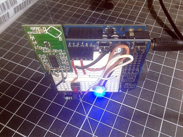
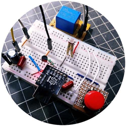
The existing circuit configuration allows you to enable driveway light(s) by temporarily short-circuiting the sensor input connector pins. Therefore, you can use an ordinary mechanical push-on switch to test your prototype as done by me.
However, the best pick for the driveway sensor in the real-world would be something similar to a pneumatic road tube.
Road tubes are widely used to detect vehicle axles by sensing air pluses that are created by each axle strike of the tube in the roadway. This air pulse is then sensed by the unit and is recorded or processed to create volume, speed, or axle classification data. Usually, one road tube is used to collect volume, and two road tubes are used to collect speed and class data.
Further, read https://en.wikipedia.org/wiki/Traffic_count
Luckily, the process of preparing a road tube sensor setup is not very difficult:
- Install road tube on the driveway
- Plug the end of road tube into its sensor
The air pulses generated in the road tube as vehicles drive over the tube activates the road tube sensor

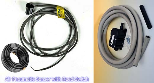
Piezo sensors are commonly employed to convert the air pulse into an electric/electronic signal. But simple momentary switches/sensors for pneumatic road tubes are also available. Below you can see such a small air pneumatic sensor with reed switch output.
Pneumatic road tube mechanism has for many years been a popular method of vehicle sensing on low volume roads and driveways. In this method, one or more rubber hoses are stretched across the path and connected at one end to a tube sensor (the other end of the tube is sealed). When a pair of wheels hits the tube, air pressure in the squashed tube activates the tube sensor which registers an event. At least one road tube is required for each direction on every path at which you want to detect vehicles.
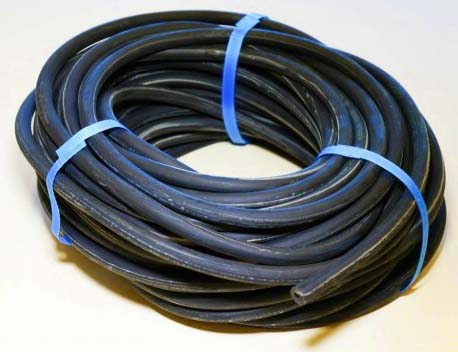
In short, a pneumatic road tube sensor sends a burst of air pressure along a rubber tube when a vehicle’s tires pass over the tube. The pressure pulse closes an air switch, generating an electrical signal that is transmitted to a counter or analysis software.
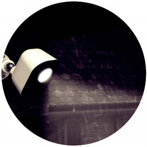
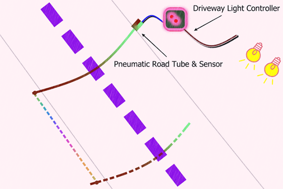
Below you can see a driveway setup pointer for the automatic driveway light controller project presented in this post.
Just a side note: Despite my best efforts, I could not buy a small pneumatic switch/sensor as our Indian online sellers did not stock it well. Actually, I found some in a local storefront at a higher price than anywhere else in the world, but don’t want to buy at that price!
Apart from pneumatic road tubes, there are a surprising number of methods available today to detect vehicles on roads and driveways, such as piezoelectric sensors, inductive loops, magnetic sensors, doppler/microwave radar sensors, passive infrared motion sensors, acoustic detectors, etc. I will come up with a few do-it-yourself projects based on some of these wonderful ideas later.

Credits & References