PID Controller is the most common control algorithm used for more precise and accurate control of various parameters in industrial automation & applications. Most often these are used for the regulation of temperature, pressure, speed, flow, and other process variables.
A PID (proportional–integral–derivative) controller continuously calculates an error value as the difference between the desired setpoint (SP) and a measured process variable (PV) and applies a correction based on proportional, integral, and derivative terms (denoted P, I, and D respectively), hence the name (https://en.wikipedia.org/wiki/PID_controller).
Of course, PID is a bit complex topic, but if you strive to learn its basic secrets and want to try something smaller and cheaper at home, the Arduino microcontroller provides an easy and inexpensive platform for you. So, I decided to prepare this Arduino PID primer for the novices in particular. Okay, let’s see how the Arduino PID controller works…
Arduino – Software (Experiment 1)
This is not to discourage you, but there’s no sense in reinventing the wheel. So, for an easy start, you can follow a precooked code which’s preferably supported by a dedicated Arduino library. Certainly, coding your own PID control loop isn’t that hard, but there’re a number of significant things to take into account.
So, download and install this Arduino PID Library at first. You can grab the library from https://github.com/br3ttb/Arduino-PID-Library/archive/master.zip. The library installation procedure varies from the operating system to the operating system. Anyway, here you can find something helpful https://www.arduino.cc/en/guide/libraries
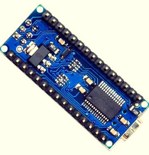
After the successful initial software preparation, just upload the code provided at the bottom of this article to your Arduino Uno or Nano board– take your pick.
#include <PID_v1.h>
#define SEN_IN 0 // A0 LDR + 10K RESI
#define ACT_OUT 9 // D9 LED + 220R RESI

double Setpoint, Input, Output;

double Kp = 0, Ki = 5, Kd = 0;

PID myPID(&Input, &Output, &Setpoint, Kp, Ki, Kd, REVERSE);

void setup()
{

  Input = analogRead(SEN_IN);

  Setpoint = 50;

  myPID.SetMode(AUTOMATIC);

  myPID.SetTunings(Kp, Ki, Kd);
}

void loop()
{

  Input = map(analogRead(SEN_IN), 0, 1024, 0, 255);

  myPID.Compute();

    analogWrite(ACT_OUT, Output);

}
Arduino – Hardware (Experiment 1)
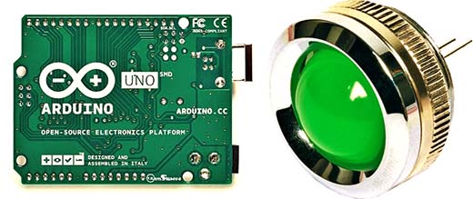
Admittedly, the simplest PID control experiment that can be carried out with an Arduino is to regulate the brightness of a light-emitting diode based on the light level that is sensed by a photoresistor i.e., one LDR as a light sensor and one LED as the light source.
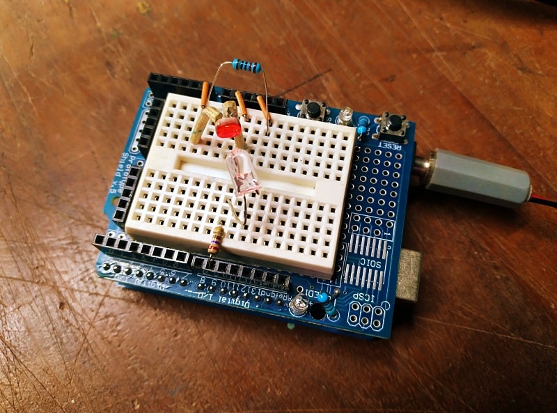
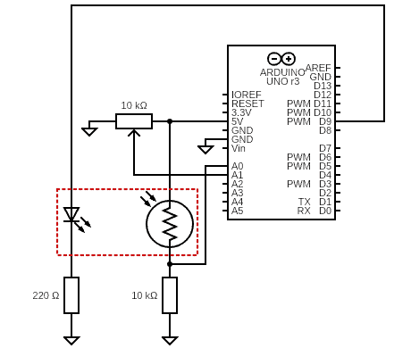
This is the proposed scheme of the basic Arduino Uno PID hardware setup. This scheme uses one 5mm ultrabright red LED and one GL5528 LDR as the light source and light sensor components respectively. You should closely place your LED and LDR so that the LDR aims into the LED output aright.
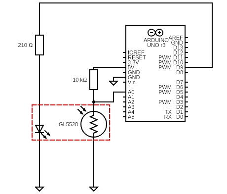
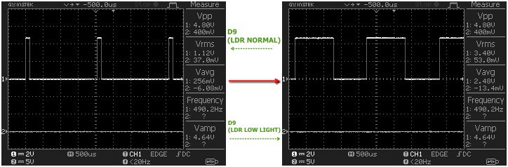
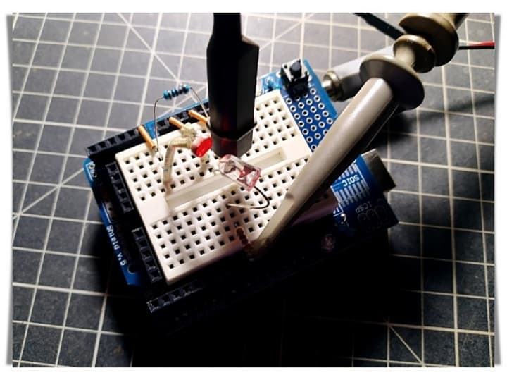
When you disrupt the LDR in your prototype with a translucent film, you can clearly see that the setup tries to maintain the brightness of the LED at the setpoint (50) by managing the control value (lamp brightness increases when photoresistor gets low light and vice versa).
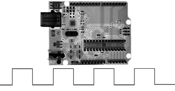
See the oscillograms:
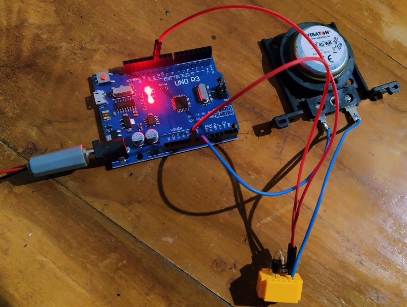
I just simply assembled everything on an Arduino Uno Prototyping Shield, and the quick setup came out like this:
Arduino – Hardware & Software (Experiment 2)
Now to a bit advanced experiment. You can use the same hardware setup prepared before but you should add a potentiometer (or trimpot) to the existing hardware assembly as depicted in the below scheme.
With the LED close to the LDR, tune the potentiometer. This should increase and decrease the brightness of the LED. If you move the LDR away from the LED, you can see that the PID loop should try to compensate and turn up the brightness to match the pre-set point. During the test, make sure that strong ambient light does not fall directly on the LDR. Otherwise, it will adversely affect the test setup.
You can download a copy of code required for this experiment from https://github.com/bcomnes/315-lab-microcontroller/blob/master/code/pid_led_set_serial/pid_led_set_serial.ino
The line in the code PID myPID(&Input, &Output, &Setpoint, Kp, Ki, Kd, DIRECT); set up the PID library to use a PID process called myPID. When you call myPID.Compute(); , myPID will take the variables Input, Setpoint, Kp, Ki, and Kd subsequently, and use them in its calculation, and then write whatever it determines to Output. The DIRECT simply tells your PID which direction you are working in. If for instance, the PID loop goes to make the LED dimmer when it should actually get brighter, you would change DIRECT to REVERSE.
At this stage it is possible to implement PID control to a system by tuning the three constants until the desired response characteristics are obtained. You are free to play with disparate values of Kp (proportional gain) and Kd (differential gain), but these variable are best left set to 0.
What’s Next?
A while ago, I realized the need for a temperature-based control of the heater in my homemade water heater. Many similar projects exist on the internet, but I planned to make my own. What I wanted was something that could find the right power level for the heater, and maintain that to provide a near-constant water temperature, and I thought that the PID might be exactly what was necessitated. So, a simple PID regulator has been designed that measures water temperature and adjusts the heater accordingly. The experiment is still in progress – more on that later.
Nice article and well explained.
Shashi Kiran: Thank You! While this guide is intended to help you get into the PID secrets, this is not an exhaustive article. I’ll come up with more PID tutorials later. So please watch this space often to get good updates, and share any topics you want me to cover. All the best 💖