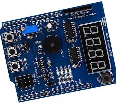
 I have just chanced the need to read some sensors for another personal project. However, the project needs a couple of blinkers and beepers apart from the intended sensors. So, I figure to just use a cheap Arduino Multifunction Shield (MF Shield) I have on hand to begin with. Nevertheless, it does have a bunch of dandy components atop of the compact circuit board. Before starting the new project, I have searched the internet about exploiting the MF shield extensively but not able to get a rich collection of application notes. So, I also decided to prepare anew multifunction shield primer for beginners. First off, this one is a bit different from what I posted before some years (https://www.electroschematics.com/getting-started-with-the-arduino-multifunction-shield/).
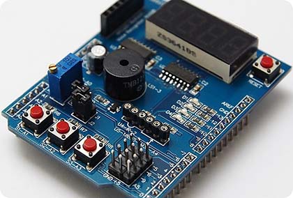
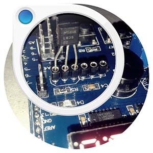
The Arduino MF shield might look scary ab initio but it’s rather easy to use the shield if you know right from wrong. So, let’s start with its complete schematic, borrowed from web, and redressed by me. You should take note that that the temperature sensor socket’s pin assignment is in the correct order for DS18B20 only. If you’re using an LM35 temperature sensor, the sensor must be mirrored i.e. plug it in the socket with its label side looking toward the top of the shield. Similarly, the socket for the infrared receiver needs a bit of attention. It’s readied for today’s common infrared receivers (TSOP1838, VS1838, HS0038, etc) – definitely not for the designated SFH-series (at least applicable to my shield).
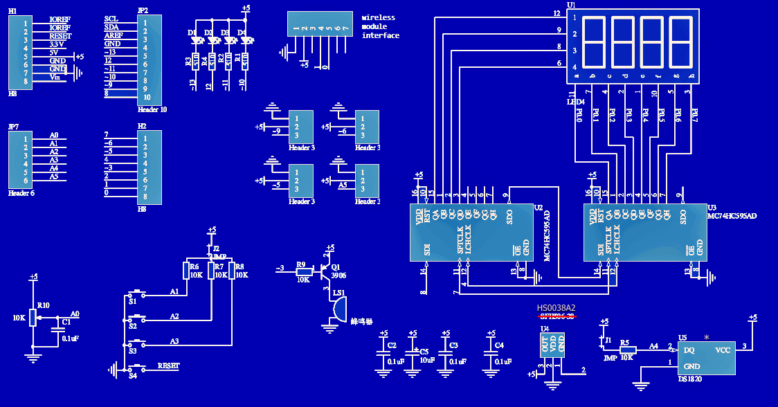
When you insert the MF shield into Arduino, the shield components are linked to Arduino’s I/Os as follows:
- Push buttons S1-S2-S3 to A1-A2-A3 respectively. S4 is linked to Reset
- LEDs D1-D2-D3-D4 to D13-D12-D11-D10
- Piezo Buzzer to D3. There’s a transistor circuitry to drive the piezo buzzer (active low)
- Infrared receiver (U4) socket’s output to D2
- Temperature sensor (U5) socket’s output to A4
- Trimpot (10K) wiper to A0
- The 4-digit LED display (3641BH) is driven by 74HC595 ICs (x2). And Arduino I/Os D4-D7-D8 (Latch-Clock-Data) are reserved for the LED display driver ICs
- The 3-pin headers to D5-D6-D9 (PWM) and A5
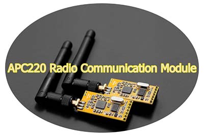
The “wireless module interface” socket pins to D0-D1 (Rx-Tx). As far as I know, this socket is intended for the APC220 shield
- 74HC595 Datasheet https://www.onsemi.com/pub/Collateral/MC74HC595-D.PDF
- DS18B20 Datasheet https://datasheets.maximintegrated.com/en/ds/DS18B20.pdf
- LM35 Datasheet https://www.ti.com/lit/ds/symlink/lm35.pdf
- HS0038A2 Datasheet https://www.puntoflotante.net/VISHAY-INFRARED-RECEIVER-HS0038A2.pdf
- APC220 Datasheet https://image.dfrobot.com/image/data/TEL0005/APC220_Datasheet.pdf
Before diving into complex matters, you should need to consider a few things. At first, if you have not already done so, get ready to download and install the necessitated Arduino MF Shield Library from this link http://files.cohesivecomputing.co.uk/MultiFuncShield-Library.zip
Although it isn’t strictly necessary to use always, it’d be better to install these Arduino Libraries as well: “Timer One” (https://github.com/PaulStoffregen/TimerOne) and “Wire” (https://www.resistorpark.com/content/Arduino_Libraries/wire.zip)
Now, upload the following piece of code to the associated Arduino Uno board to read MF shield’s 10K trimpot value and display it on the 4-digit LED display. After uploading the code, simply turn the trimpot clockwise/counterclockwise to see the (0-1023) readings on the bright red display!
#include <MultiFuncShield.h>
#include <TimerOne.h>
void setup() {

  Timer1.initialize();
  MFS.initialize(&Timer1);
}
void loop() {

  MFS.write(analogRead(POT_PIN));
  delay(100);
}
Okay? Great! Now you have it. It’s damn easy to play with this particular multifunction shield and I was able to get it running in few minutes of work. So, get coding and have fun!
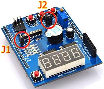
Oh, I almost forgotten that! The jumper J1 provided in the shield is to enable/disable the 10K pullup resistor wired at the output of the temperature sensor socket. Likewise, the next jumper J2 lets you enable/disable the pullup resistors (10Kx3) wired to analog inputs (A1-A2-A3).
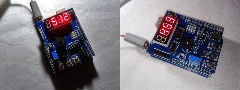
A pair of casual snaps from my workbench – the aforesaid trimpot test:
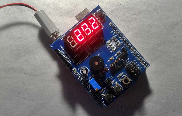
Nevertheless, now you have a compact Arduino MF shield that has a number of peripherals like switches, indicators, sounder, display, etc. And obviously, a great Arduino MF library to start the real play. As said before, you can of course do your projects without the MF shield library. But see, it will help you to reduce the time and effort behind an Arduino project. For example, below you can see a piece of code to build your own LM35 temperature sensor based digital thermometer. The project needs just one LM35 and a few lines of code (Thanks to Kashif Baig)!
So, open the jumper J1, insert LM35 in its socket aright, and upload the given code. Yes, you’re done!
#include <TimerOne.h>
#include <MultiFuncShield.h>

void setup() {
Timer1.initialize();
MFS.initialize(&Timer1);

MFS.initLM35(SMOOTHING_MODERATE);
// LPF (low pass filter-moderate level) in use, and initialized!
}
void loop() {

int tempCentigrade = MFS.getLM35Data();
MFS.write((float)tempCentigrade / 10, 1);  // Display temperature in degree C to 1 decimal place
delay(100);
}
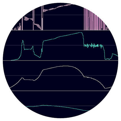
As you’re aware of, a common problem in Arduino sensor projects working close to power circuits is the presence of parasitic signals. Luckily, a low pass filter (LPF) can be employed to filter out such parasitic signals. In the library-supported above code, moderate level LPF is called in to smooth the noisy temperature sensor output.
Related links (randomly picked):
- https://elvistkf.wordpress.com/2016/04/19/arduino-implementation-of-filters/
- https://www.megunolink.com/articles/coding/3-methods-filter-noisy-arduino-measurements/
- https://github.com/MartinBloedorn/libFilter
Well, that’s it for today! If you experience any difficulties, please leave a comment below, and I’ll get back to you as soon as I can. ’til next time!