 With one of my automotive electronics projects I am wanting to add a couple of light-dependent resistors (LDRs), also called as photoresistors, and to do that I did a thorough search to discover the best LDRs available through web merchants in front. While Googling, I came across a ‘new’ photoresistor described by most sellers as “5800B Light Dependent Resistor”!
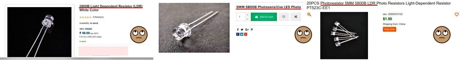
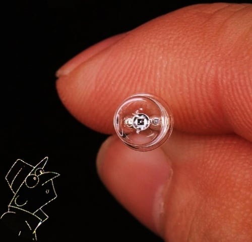
Since its shape and description seems a bit suspicious, I also included it in my shopping list, and later gathered a bunch of those curious light sensors from three different web merchants. This is the key specifications of the 5800B LDR provided by a prominent Indian online retailer.

Rather unsurprisingly, I was informed subsequently by a Chinese seller that 5800B is an LED-shaped 5mm photodiode. Its long lead is the anode (A) and short lead is the cathode (K). The seller also emailed a few credible images to justify his claim.
Sadly, both descriptions are simply cosmetic and utterly wrong! The 5800B is definitely not a light-dependent resistor (LDR)! In question? Okay, get ready to read the story of exposure!
5800B Light Sensor – Quick Examination
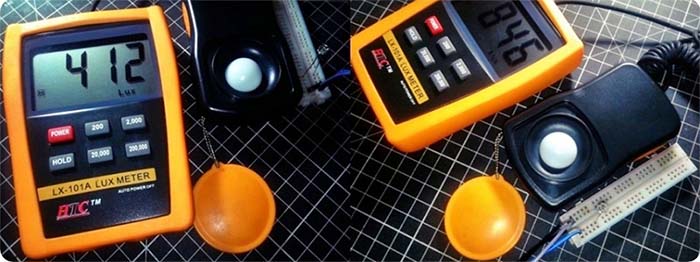
For the quick examination, I used a randomly picked sensor from my limited collection and used a DMM to simply measure its resistance when exposed to extreme dark and light conditions. I also used a lux meter to measure the ‘test’ light levels. And it’s observed that the 5800B light sensor has a distinct polarity. Thus, it’s certainly not a photoresistor (LDR). Here’re the readings:
| 5800B Light Sensor | Extreme Dark Resistance(Ω) | Extreme Light Resistance(Ω) |
|---|---|---|
| Lead (L) = + , Lead (S) = - | Infinite | <100K |
| Lead (L) = - , Lead (S) = + | >10M | 4K – 2K |
So, it’s roughly assumed that the 5800B light sensor is a generic phototransistor or a photodiode!
Next, I took some more readings with the same DMM but dialed to diode test mode. See the readings:
| 5800B Light Sensor | Extreme Dark Condition | Extreme Light Condition |
|---|---|---|
| Lead (L) = + , Lead (S) = - | 0V/OPEN | 0V/OPEN |
| Lead (L) = - , Lead (S) = + | 0V/OPEN | 750mV – 200mV |
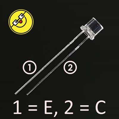
Here in this particular test reports, the extreme dark level denotes 0 lux and the extreme light level denotes 400-1000 lux. And, as you can see, the light sensor gives a sensible response only when its longer lead (L) is negative (-) and shorter lead (S) is positive (+). Therefore, 5800B is a phototransistor – its longer lead is emitter (E) and the shorter lead is collector (C)!
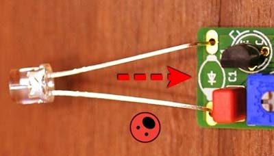
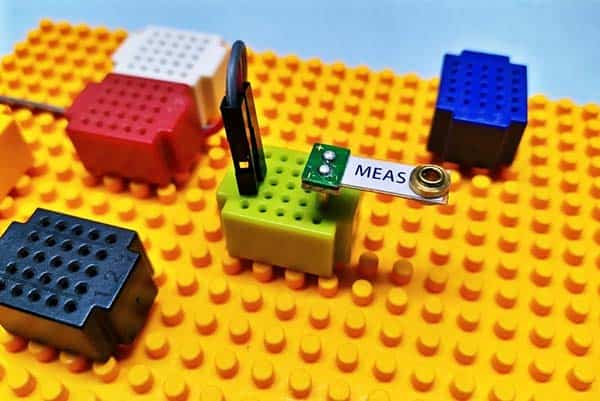
Below you can see partial snaps of my quick examination setup.
5800B Light Sensor – Further Confirmation
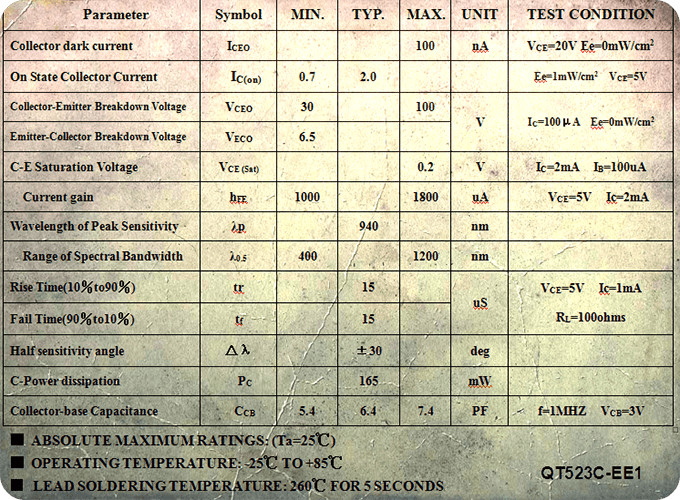
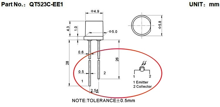
Thanks to Yoycart.com. According to their message, 5800B is actually an NPN phototransistor that has a part number QT523C-EE1. Below you can see its key specs.
5800B Light Sensor – Arduino Analog Read
Since I wanted to verify that it’s actually true, I rigged up another quick examination setup using an Arduino Uno and Uno Protoshield, so that from its output I can see the readings through Arduino’s serial monitor. Before jumping into that game, let me share some useful things about practical applications of common phototransistors.
A phototransistor converts the photons striking onto its base area into an effective base current that controls its collector current. In principle, there’re two modes that a phototransistor can be used in – switch mode and active mode, which is usually set by the value of the associated load resistor. In switch mode the phototransistor is either on or off state, whereas in active mode the output is variable, giving a value related to the amount of light. One drawback of the active mode is that the phototransistor has a non-linear response to light, as light increases beyond a certain level its output will suddenly jump and then flatten out.
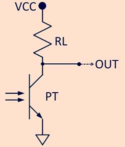
Above, the phototransistor circuitry (active mode) is operated in common-emitter configuration (phototransistors can be operated in the common-collector configuration as well). As the power of the light striking on the phototransistor increases, the collector current (Ic) increases, causing the collector voltage to drop due to the voltage drop across the load resistor RL (collector resistor). The collector current reaches an upper limit when the phototransistor enters its saturation region in which the collector-emitter voltage (Vce) reaches approximately 200mV and the remaining voltage drop from the VCC power supply appears across RL. Any further increase in light power applied to the phototransistor will not increase the collector current any more beyond this point. In short, as the light level increases the output voltage level drops!
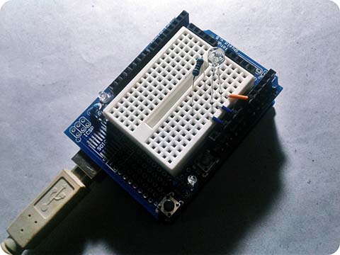
If you an Arduino Uno/Nano board, then you should be able to rig up the test circuit (look below) and view the Arduino’s output using the Arduino software’s serial monitor. You can write your own Arduino Sketch (the code), or you can modify the crude one provided at the end of this post.
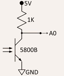
While making your test circuit, keep in mind that the 5800B phototransistor’s positive (+) lead, or collector, is shorter than its negative (-) lead, the emitter. For the setup to work correctly, you’ll have to orient it aright, else you’ll get week/false readings!
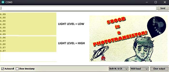
This the test result as displayed by my Serial Monitor. See, the output voltage value is close to the VCC (5V) when the 5800B phototransistor gets only very low light, and the output voltage drops to about 800mV while it’s exposed to very strong light. Exactly as described earlier!
My Arduino test setup looked like this:
#define photoSensor 0

void setup(void) {
Serial.begin(9600);
Serial.println();
}

void loop(void) {
int inRead = analogRead(photoSensor);
float inVolt = inRead / 1024.0 * 5.0;
Serial.print(inVolt);
Serial.println();
delay(100);
}
More projects later… but for now, you can start your play with the ideas presented here!
Will this unit act as a variable resistor with changing light levels: say from an LED ?
@Gavan: You can try it. See this application pointer https://aws1.discourse-cdn.com/arduino/original/4X/1/a/e/1aeeff1164a1ad61965781ee79f8566737cf287d.jpeg
But it is better to use a standard “photoresistor” for your specific purpose. Thanks!
So, in short, does this mean that as light brightness decreases, voltage decreases and as light brightness decreases, voltage increases?
@Joshua: In the given Arduino setup, the output voltage of the 5800B sensor circuit increases when the phototransistor gets only very low light, and the output voltage decreases while it’s exposed to very strong light.