The moment you get a MAX30100 pulse oximeter and heartrate sensor breakout board, you can move on to the process of making your own perfect pulse oximeter. But is making one as easy as you think? Perhaps not!
The MAX3010x series sensors provide complete optical-module solutions to ease the design-in process for mobile and wearable fitness and health devices. It’s worthy to note here that pulse oximetry is a non-invasive method of measuring an individual’s blood oxygen saturation levels. Oxygen saturation levels, referring to the ratio of oxygenated hemoglobin to total hemoglobin in the blood, can aid in the detection of hypoxemia, deteriorating organ function, and even cardiac arrest. Therefore, a non-invasive solution to measure oxygen saturation levels, as provided by MAX3010x sensor, is of medical importance. Additionally, there’s an inherent heart rate (HR) signal associated with pulse oximetry measurement, allowing the users to obtain this as well.
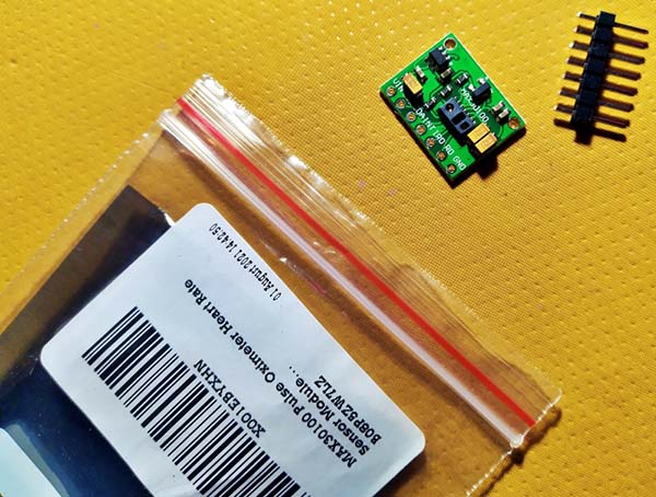
But again, it’s not as simple as it sounds, especially if you choose the cheaper Chinese (green-colored) MAX30100 sensor breakout board/module.
Oh, I’m not trying to deter you, but that’s the fact. Let me explain a few things about it.
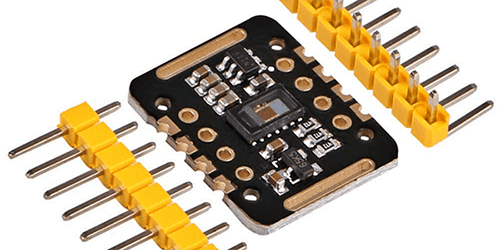
The MAX30100 is in fact integrated pulse oximetry and heart rate monitor sensor that combines two LEDs, a photodetector, optimized optics, and low-noise analog signal processing to detect pulse oximetry and heartrate signals. The wearable health sensor operates from 1.8V and 3.3V power supplies and can be powered down through software with negligible standby current, permitting the power supply to remain connected at all times. Now look, the device has two LEDs – one emitting red light, another emitting infrared light. For pulse rate, only infrared light is needed, but both red light and infrared light is used to measure oxygen levels in the blood.
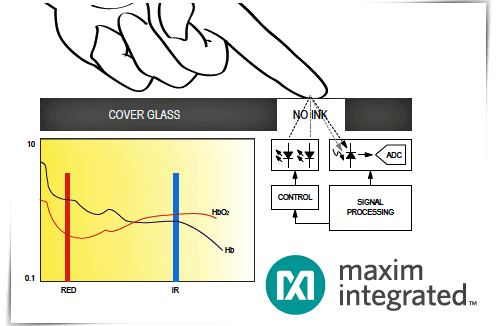
See, the setup is like the one used for transmissive pulse oximetry except the photodiodes are placed on the same side of the test zone as the LEDs. The LED light illuminates the skin while the reflected signal is monitored for changes in light absorption.
Of course, there’re a lot of MAX30100x sensor modules available, but from now on my writing will focus only on the aforementioned “green” version which is the most popular among others. So, get ready to check it out.
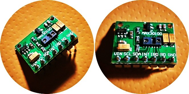
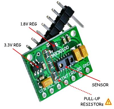
To be clear, the MAX30100 sensor will work as promised by its creator, but the real problem is the design of the green module (RCWL-0530) where it’s mounted. Below is an annotated image of the MAX30100 module.
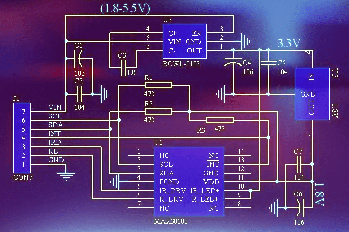
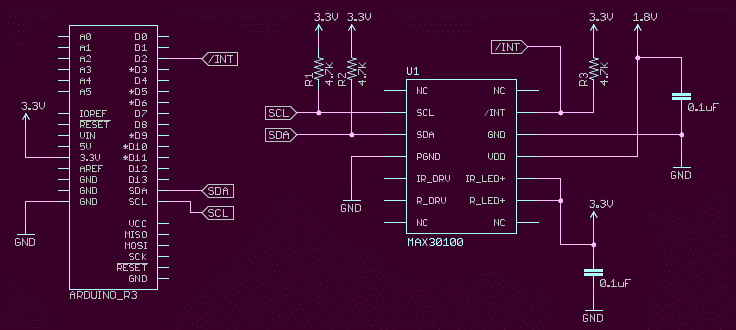
Next is its basic schematic. When you take a closer look, you can see that the 4.7KΩ I2C pull-up resistors (R1-R2), and the INT pull-up resistor (R3), all are wired to the 1.8VDC line! Then how does it works with a 5V microcontroller like our Arduino Uno/Nano?
The resistors that are commonly seen on I2C circuits sitting between the SCL and SDA lines and the positive rail are called I2C pull-up resistors. A pull-up resistor is used to provide a default state for a signal line or general-purpose input/output (GPIO) pin.
When going to look at I2C logic-high (H) and logic-low (L) levels, L = 0.3 x VDD & H = 0.7 x VDD. So, when you hook the MAX30100 sensor module up to your 5V Arduino, you need to ensure that your SCL and SDA lines are above 3.5V to register as a logic-high signal, and below 1.5V to register as a logic-low signal. If so, how does this funky module get worked with a 5V microcontroller?
Luckily, if you’ve enough dexterity and patience, this fatal mistake can quickly be fixed by cutting a track and make a jumper as shown in the below figure. The jumper does not need an insulated wire but a piece of magnet wire would be fine.
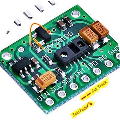
As can be seen in some forum posts, this trick may not work well in some situations, but I have not yet gone deeper into this topic. Another proven idea is to desolder those three 4.7KΩ pull-up resistors and wire them externally (3.3V pull-up) on the microcontroller’s GPIOs. See the below reference diagram.
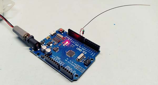
When your mollified MAX30100 module is ready to work with an Arduino, just follow this wiring pointer, and use this MAX30100 library (https://github.com/oxullo/Arduino-MAX30100/). The library provides a couple of examples, just start with the “MAX3100_Minimal” example sketch.
| MAX30100 Module (RCWL-0530) | Arduino Uno/Nano |
|---|---|
| VIN | 5V |
| GND | GND |
| SDA | A4 |
| SCL | A5 |
| INT | D2 |
In the end, all you need to do is place your finger on the top of the illuminated sensor window to see the result thru the serial monitor. Note, if the red LED is not turning on, and you’re getting the failed message on the serial monitor, it might be a power issue. If so, try to tweak the code to lower the LED current (Default is 50mA).
On tenterhooks?
Whilst Maxim Integrated stopped the production of MAX30100 in favor of MAX30101 and MAX30102, the MAX30100 sensors and modules are still broadly available. Even so, in a future post, I’ll give you a brief introduction about them all, and through that post, you will get the complete project details of a do-it-yourself wearable health device. Stay in the know!