Since every machine has its own vibration signature, drifts in a machine’s vibration can indicate potential faults. There’re multiple types of vibration sensors available to keep tabs on a machine’s vibration, and a widely used vibration sensor is the piezoelectric vibration sensor. A piezoelectric vibration sensor (also called piezo vibration sensor) mounted on a machine can detect when and how the machine’s vibration pattern changes.
Oh, this post is not about using piezo vibration sensors for machine condition monitoring or similar tasks because my real intention at this time is to give you a quick introduction to the MiniSense 100 Vibration Sensor (www.meas-spec.com) which’s very popular in the hobby electronics/robotics world.

MiniSense 100 – Functional Description
The MiniSense 100 is a low-cost cantilever-type vibration sensor with a flexible PVDF sensing element loaded by a mass to offer high sensitivity at low frequencies. Horizontal and vertical mounting options are offered and its pins are solderable.
The MiniSense 100 acts as a cantilever-beam accelerometer that can be used to detect either continuous or impulsive vibration or impacts. When the beam is mounted horizontally, acceleration in the vertical plane creates bending in the beam, due to the inertia of the mass at the tip of the beam. Strain in the beam creates a piezoelectric response, which may be detected as a charge or voltage output across the electrodes of the sensor.
Salient Features:
- High Voltage Sensitivity (1V/g)
- Over 5V/g at Resonance
- Horizontal or Vertical Mounting
- Shielded Construction for Improved RFI/EMI Rejection
- Solderable Pins, PCB Mounting
- Low Cost
- Analog Output
- < 1% Linearity
- Up to 40Hz (2400 RPM) Operation Below Resonance
Typical Properties:
- Voltage Sensitivity (open-circuit, baseline): 1.1V/g
- Charge Sensitivity (baseline): 260 pC/g
- Resonance Frequency: 75 Hz
- Voltage Sensitivity (open-circuit, at resonance): 6V/g
- Upper Limiting Frequency (+3 dB): 42Hz
- Linearity: +/-1 %
- Capacitance: 244pF
- Dissipation Factor: 0.018
- Inertial Mass: 0.3gram
Note that, for excitation frequencies below the resonant frequency of the sensor, the device produces a linear output governed by the above-mentioned baseline sensitivity but sensitivity at resonance is significantly higher.
MiniSense 100 – Random Ramblings
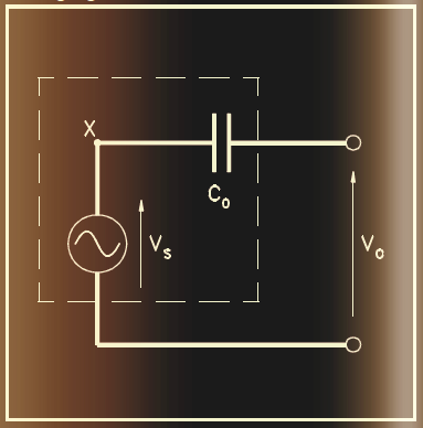
The MiniSense 100 sensor acts electrically like an “active” capacitor, so it may be modelled as a perfect voltage source with an output voltage proportional to applied acceleration in series with the quoted device capacitance. And, any external input or load resistance will form a high-pass filter, with a roll-off frequency calculated from the formula: f(c) = 1/(2πRC).
The impedance of the sensor is approximately 650 MΩ at 1Hz.
Now we’ve to do a little bit of maths
Let’s assume we want the cut-off frequency to be at 10Hz. At this point, the magnitude of the sensor signal will fall to 0.707 level (-3dB roll-off). Using the above formula, we can calculate the required load resistor value: R = 1/(2πfC) = 1/(2πx10x244x10-12) = 65MΩ.
And, a 650MΩ load resistor is required for 1Hz!
This obviously denotes that to get a low-frequency response, we need a high-value load resistor or high input resistance for the next stage!
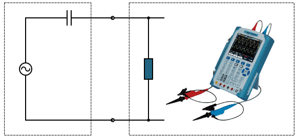
Take note, the oscilloscope is a resistive load
In most instances, the first evaluation of a sensor starts with connecting it to an oscilloscope via a scope probe. Under normal electronics circumstances, the scope probe can be considered to be an “infinite impedance”, so its effect on the sensor under test can be neglected.
But it’s not so with a piezo film sensor in many cases!
See, a typical scope probe, when plugged into an oscilloscope, have an effective resistance of 1MΩ. Usually, an oscilloscope and its probe are modelled simply as a pure resistance, although in reality there will be a very small capacitance (30pF to 50pF) associated with the probe and the cable. But this can be neglected if the sensor’s capacitance is significantly higher in value.
In short, if we connect the MiniSense 100 to an oscilloscope, we get a high pass filter (HPF).
In front of a dangerously high voltage
A very crucial point to note down at this time is that the sensor output can reach over ±80V on high accelerations or when vibrating at its resonant frequency (you might get more on a more substantial impact). Therefore, you cannot plug it directly into a microcontroller or other low voltage circuits, it will potentially damage sensitive parts. You’ve been warned!
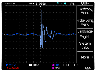
MiniSense 100 – Quick Test

Probably there’s no need to explain how I did the quick test. As you can see in the oscilloscope capture below, the sensor output is a sine wave that decays rapidly. Even under a lame impact, it delivered a reasonably high output voltage (~7V p-p).
MiniSense 100 – Get Ahead!
The MiniSense 100 seems like a great sensor for detecting accelerations, shocks, vibrations, etc. I hope this post inspires you to tackle your own vibration sensor projects. Ultimately, it’s up to the maker (yes, you) to evaluate the sensor’s response and use it in a project.
After the bulk of this post had been drafted, I built a simple shock/impact/vibration sensor alarm using MiniSense 100 and ran a couple of field trials successfully. Well, check back later to get it!