Prolonged blackouts have always been an annoyance, but with the help of today’s portable inverter lamps/bulbs, tackling them has become much easier. Below you can see such an affordable LED Inverter Lamp from Osram (India).
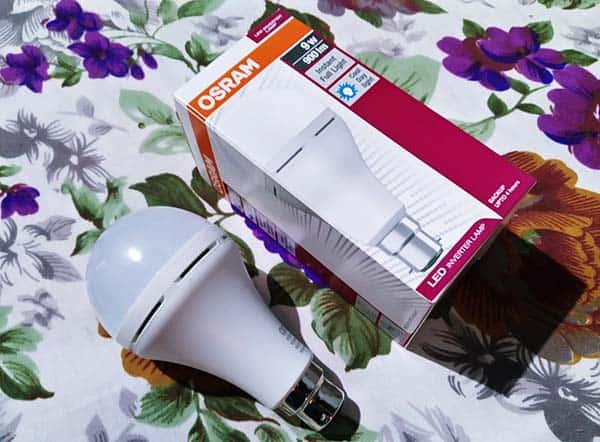
This is an AC230V/9W LED inverter lamp for indoor use which features a backup time of up to 4 hours. The lamp is very similar to every other regular LED bulb, although scaled up just a little bit more due to its size. The lamp measured approximately 130 grams on my digital kitchen scale, which I feel is on the light side.
Note that this LED inverter lamp functions with the help of an internal battery, charging itself when switched on during the availability of power supply. The recommended charging time for battery mode is 8 hours.
As soon as the electricity is disconnected, the backup lamp mechanism springs into action and brightens up the space. While the lamp operates with an output of 9W during power supply, it works at a reduced lumen level of 40-50% at times of no electricity supply.
Okay, now let me share the teardown notes of a Chinese unbranded LED Inverter Lamp!
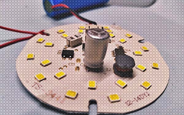
Surprisingly, opening the lamp proved to be fairly easy. The front part (which holds the entire electronics circuitry and the diffuser dome) separated from the lamp base with less force than other models, perhaps due to the way it’s tamped down.
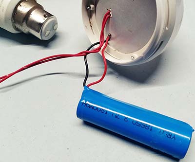
What visible in a flash at the time was one 18650 lithium-ion battery pack (3.7V/1800mAH)
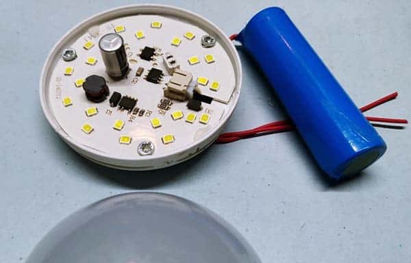
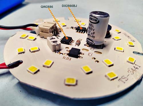
Inside the detachable diffuser (frosted plastic dome), there’s an MCPCB containing the LEDs, with two ICs and a couple of passive components on the circuit board as well. A closer look shows that the light source comprises of twenty-four cool white SMD LEDs.
The AC230V input segment of the circuitry has an integrated bridge rectifier MB10F (https://www.diodes.com/assets/Datasheets/MB10F.pdf) which’s employed together with a radial 4.7uF/400VDC polarized capacitor for doing the high-voltage AC to DC conversion.
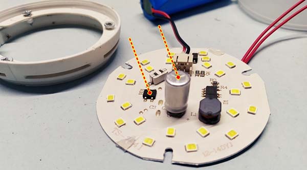
Another closer look shows that the ICs mounted on the board are QW2886 and DX2866 I’ve not seen any of these used in the past.
However, after a thorough Google search, I found that QW2886 is a LED driver designed for emergency lighting/standby lighting applications. The QW2886 IC employs a patent-protected mains line detecting methodology to control and drive emergency lighting systems, without any peripheral components. It also integrates a precise single lithium‐ion/polymer battery management mechanism to protect the battery, including over-current protection, overcharge protection, over-discharge protection, battery reverse protection, and short circuit protection.
Below you can see its typical application circuit (Thanks to SincereTek).
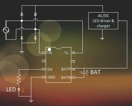
Keep note that the output pin EN of this ASIC is turned on if the resistance between VL and VN (AC input pins) is less than the threshold resistance, while there is no AC power signal. If the AC power is detected or the resistance between VL and VN is larger than the threshold, the EN pin is high impedance state.
Likewise, the DX2866 is a high precision buck constant current LED driver, which operates in critical conduction mode and is suitable for 85VAC to 265VAC universal input offline LED lighting. It also offers protections to improve the system reliability, including LED short circuit protection, and thermal regulation function.
Here’s its typical application circuit:
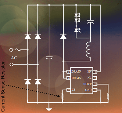
The current sense resistor used in our inverter lamp circuit board appears to have two parallel connected 1.74Ω chip resistors. The drum core/dog bone inductor is a 1.2mH type, and the diode is a fast rectifier – ES1J (https://www.onsemi.com/pdf/datasheet/es1j-d.pdf). That’s all.
In conclusion
On the whole, a fairly decent LED inverter lamp design, it seems!
But on a final inspection, it’s observed that the configuration of both ICs in this design has some minor deviations when comparing with the official application examples. As a result, the actual circuit seems a little different from what I imagined (more on this later).
Perhaps, it will not be a worrying issue, but it does differ from some other Chinese LED inverter lamp designs. However, whether the tweak is good for reliable performance is not known.
On a different note, now I want to reuse a few components from this circuit board and try making something new out of it (this certainly warrants further investigation). As far as I can tell, the thing that is reusable quickly is probably the QW2886 IC.
So hopefully when I’m armed with enough knowledge about dedicated emergency lighting controllers, I can continue on the dreamt-up project. Well, keep an eye out for a future post on the topic.
Any corrections/reprimands/ideas? Just leave me a comment below!
It is very interesting and I read it fully. A decent explanation with limited even though the resources limited. Thankful for the efforts. Waiting for a detailed findings in this
@Harikrishnan: Thanks for the kind words and inspiring feedback. Glad you’re enjoying my little post and still following along on this journey. Cheers!