Although there are many dedicated sensors and sensor modules to measure current, this post describes the more orthodox method using a shunt resistor!
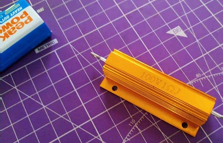
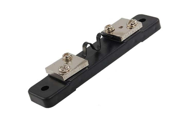
A shunt resistor is a power resistor with very low resistance especially when compared to the load and the power source. Below figure shows the typical appearance of a 75mV@50A dc current shunt resistor. It is in fact a pretty common ammeter shunt resistor that allows the measurement of current values too large to be directly measured by a particular analog of digital ammeter.
I to V Translation
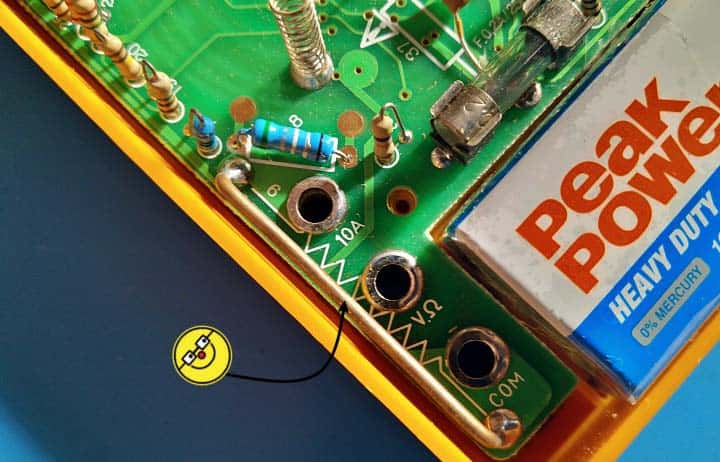
Measuring current is not as straightforward as measuring a voltage, so we need to find a convenient way to convert current into voltage, and the best basic component for current-to-voltage transformation (I-V) is a shunt resistor. That is, when a suitable shunt resistor is inserted between the power source and the load, the current that flows through the shunt resistor will produce a voltage drop across it. Below you will see a 10A shunt resistor used inside a cheap digital multimeter.
In principle, a shunt resistor (current sense resistor) is similar to a normal resistor but with very low resistance rating and high-power rating. A shunt resistor of known resistor value (R) is placed in a current conducting path so that the entire current (I) which is to be measured flows through the shunt resistor. Nowby measuring the voltage drop (V) across the shunt resistor and by using simple Ohms Law (I=V/R), we can calculate the amount of current that flows through the circuit.
Significant Parameters
The resistance value is a crucial parameter for a shunt resistor, because that value will determine how much voltage will drop during the flow of current.
Also, tolerance and power rating of the resistor are significant parameters for the sensing accuracy of a shunt resistor. Note at this point that the shunt resistor power dissipation can also be identified using the PCR (power coefficient of resistance) value of a resistor (it stands for ppm per watt and characterizes the different values of power dissipation of different value resistors).
Likewise, temperature coefficient of the resistor (ppm/°C) is the parameter that determines how much resistance will change by the changes in the temperature of the resistor. It is an essential parameter in the shunt resistor application.
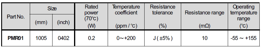
Here is a snip from the datasheet of a metal plate shunt resistor:
Shunt Resistor Location
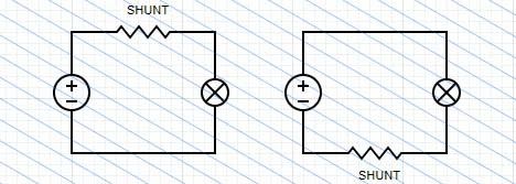
The placement of a shunt resistors can be two types, high side placement and low side placement. In high side placement, the shunt resistor is placed at the high side (+) of the load In low side placement, the shunt resistor is placed at the low side (-) of the load (see below).
Current Sense Amplifier
In a basic shunt resistor circuit, the amount of the shunt resistor voltage drop is very small, so it calls for a circuit that can amplify the voltage with a high level of accuracy. A high-precision operational amplifier (with a small input offset voltage) can then be used, and such a circuit configuration that uses a shunt resistor and an operational amplifier is called a current sense amplifier (or shunt amplifier).
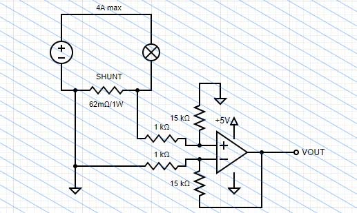
As an example, the below shown differential amplifier model amplifies the voltage drop across the shunt resistor about x15 times and outputs it (VOUT).
This method of sensing current using a shunt resistor and an operational amplifier is widely used method because it is low-cost and easy to use. I did some experiments with this idea using commonly available op amps like LM358 and MCP6002.
I will not get into more practical design details at this point but note that a cost-effective option when designing a low-side current-sensing circuit is to use an operational amplifier in a non-inverting configuration. One of the advantages of low-side current measurements is the common-mode voltage, or the average voltage at the measurement inputs is near zero.
Below figure shows the basic schematic of a typical low-side current-sensing setup using an operational amplifier.

Over and above, since input offset voltage of the operational amplifier causes measurement errors when handling little voltages, it would be better to opt for a high-precision operational amplifier with lowest possible offset voltage.
Another viable option is a zero-drift amplifier that automatically adjusts the input offset voltage.
Well, you can now measure the amplified shunt voltage value utilizing your favourite Arduino microcontroller and convert it into a current value to display.
Arduino Shunt & Little Pitfalls
Keep in mind, many of the common commercial shunts have a voltage drop of 75mV at the maximum current (50mV and 100mV versions are also available).
The Arduino has a few issues with such mV shunts because the maximum shunt output voltage range is in 50 to 100mV compared to the Arduino’s 0 to 5V range. Also the ADC (analog to digital converter) on Arduino is a 10-bit ADC. So, a 100A/100mV shunt would have a 4.88mV per step resolution, or about 5A per step.
We can however resolve this issue by utilizing an external higher bit ADC module with the Arduino. Note that with a 5V reference (VREF), a 10-bit ADC has a 4.88mV resolution while it is 1.22mV for a 12-bit ADC for the same reference.
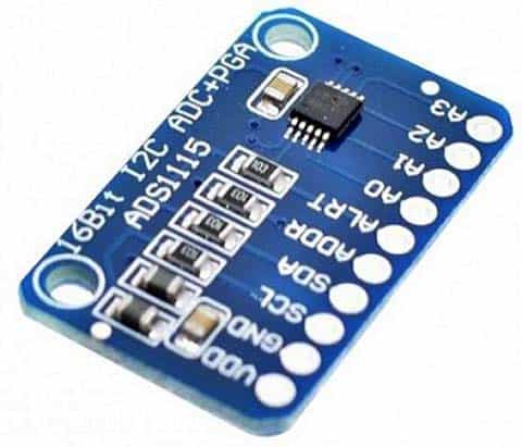
An ADS1115 (16-bit I2C ADC+PGA) module can easily be used for this (see below). Then, the rest is fairly simple.
In conclusion, shunts, unlike the solid state hall-effect type current sensors, drop a small voltage across a calibrated resistor, indicating the current being passed through the shunt. This allows a shunt to register massive amount of current, depending on its design. Current shunts are very popular and widely used in electric vehicles, sailing boats, solar/wind/hydro power systems, etc.
In the upcoming sequel of this post, you can see more pragmatic ideas about current measurements using commercial shunts and power resistors. That is it for now!