USB-C Power Delivery (PD) is a standard that supports up to 100W of power!
My first attempt in using a USB-C power adapter as a power source for my breadboard projects was met with great enthusiasm (https://www.electroschematics.com/usb-type-c-power-delivery-and-hobby-power/). It was just a breakout board from Pololu to sink ample current at 5VDC from any USB-C PD wall adapter and/or thru a USB-C PD power bank.
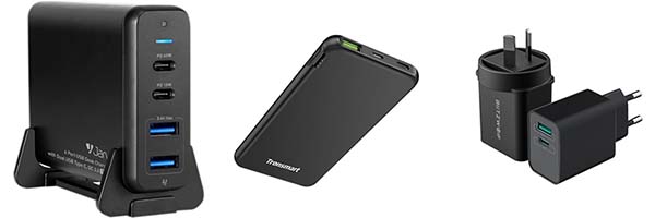
Now let’s take a look at various practical options for powering your projects using USB-C Power Delivery, ranging from prewired solutions to do-it-yourself ideas you might include in your future designs.
USB-C PD & 5V/3A
What I explained in the aforementioned previous post about USB-C PD is a simple way to get 5VDC at up to 3A by employing just two regular resistors on the USB-C connector on the end device, otherwise known as Upward-Facing Port (UFP). What I’m repeating at this time is just add two 5.1KΩ 1% resistors on both the CC lines tied to ground on the connector of your end device to get 5VDC at up to 3A.
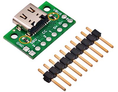
To make it simple and understandable, I’ve attached a picture below for you. So, take a look at the image of the Pololu USB-C breakout board that has the two 5.1KΩ resistors (69 B-chip resistors) on the CC (configuration channel) lines needed to draw up to 3A of current at 5VDC from the USB-C power supply source. This is absolutely essential because the host device won’t supply power until it detects a connection on the configuration channel.
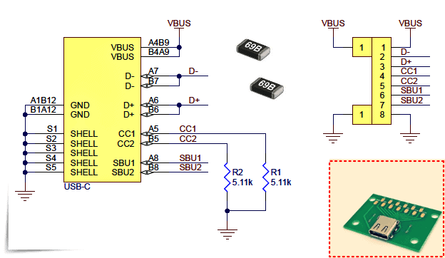
Below is a schematic diagram to help you build a USB-C PD (5V) breakout board if desired.
Now it’s important to note that USB-C Power Delivery (USB-PD) is a new protocol specification that allows for faster and more flexible charging. It’s developed concurrently with USB Type-C (USB-C) which is the physical connection, and it is a subset of the new USB 3.1 standards. The standard for USB-C devices without PD is 5V/3A, but the voltage is configurable depending on the device and can go as high as 20V/5A. Look, not all USB-C multiport wall chargers and power banks support USB-PD, nor will all USB-C devices charge with all USB-C chargers (https://www.pcmag.com/how-to/what-is-usb-c-an-explainer).
The basic gist of how the USB-C PD works is that two USB-C PD-enabled devices negotiate a power handshake when they’re plugged into each other. They discuss how much power the source can deliver, as well as how much power the other device can handle. Then they settle on a compatible rate which both the supply and device support and the charging/discharging process begins!
USB-C PD & 5V/9V/12V/20V
Now you know that the USB-C has the potential to provide much more power through the power delivery scheme. When you first plug a USB-C device into a USB-C PD power supply, the power supply will send over 5V, and this should be adequate to run the power supply circuitry and get everything started. However, your device can negotiate to receive up to 5A at 20V (100W) if the power supply can manage it. This is potentially a lot more flexible but also requires some more sophisticated electronics.
Luckily, there’re off-the-shelf “USB-C PD Trigger” boards that help do the hard work for you!
If you want to get into USB-C Power Delivery to play around with getting higher voltages and wattages, there’re countless USB-C PD trigger boards and modules from Chinese makers that suit your needs, good to up to 100W. Just make sure you got a USB-C cable and power source that can handle 100W unless you’re feeling lucky!
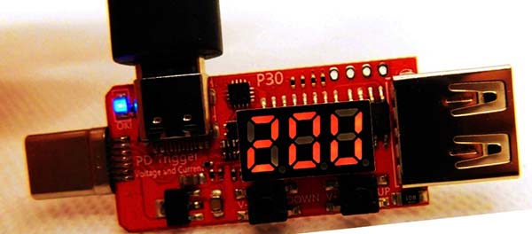
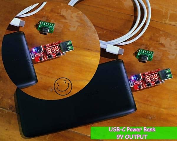
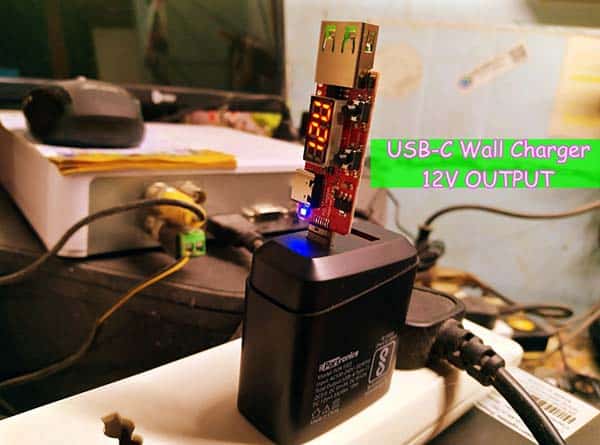
A USB-C PD trigger board exploits the USB-C PD protocols to negotiate the level of voltage we want. Such an ingenious board can simply turn a USB-C power supply into a variable universal power supply for almost any electronic device. The most common USB-C PD trigger board, like the one demoed here, usually has an onboard microcontroller that helps in negotiating for the PD protocol. It also has a USB-C male connector on one side (and a female connector on another side), a USB-A female connector, and a power supply indicator. Moreover, there’re pushbutton switches for setting the voltage you want to negotiate, and a digital display to show the final output voltage.
USB-C PD & DIY Minds!
How to build a minimal but practical USB PD stand-alone sink controller (USB-C power module)? Admittedly, this is not an easy do-it-yourself project for many, but it’s not out of the question!
At this point, here is a theoretical excerpt for your attention. See, a Downstream Facing Port (DFP) sends data, can source VBUS power, and is typically a host or a hub. An Upstream Facing Port (UFP) receives data, sinks VBUS power, and connects to a host. And a Dual-Role-Data (DRD) port can act as either a DFP or a UFP. In the case of DRD, the port’s role is determined by whether it acts as a power source (DFP) or sink (UFP) at start-up, but its function can be dynamically changed during operation if needed. The USB Type-C specifications explain different resistor values for determining whether a device is sourcing or sinking current.
Further, it should be noted, USB PD 3.0 introduced some changes to enhance power delivery and robustness of the system but has made no changes to the power rules. USB PD 2.0 and 3.0 are completely interoperable and backward compatible. Anyway, USB Type-C (1.2) without USB PD offers a maximum of 5V at 3A (15W), so it is suitable for a wide range of applications without the added complexity of USB PD.
This article will then provide guidance on how to implement practical USB Type-C and USB PD designs https://www.digikey.com/en/articles/designing-in-usb-type-c-and-using-power-delivery-for-rapid-charging
Getting back into the maker’s playground, my first try-out was with a STUSB4500 (Standalone USB Power Delivery Controller) evaluation board. A long time ago, I got that (used a bit too much) board through a social media friend abroad, and then during a careless experiment, I bricked that nifty board (http://static6.arrow.com/aropdfconversion/6025123062f9908ac39880f651d3b151282776b8/en.dm00620808.pdf).
But today, you may buy another board from here https://www.tindie.com/stores/oxplot/ to reshape your USB-C PD projects ideas (I do not have this yet).
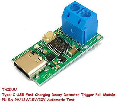
Or, opt for cheaper Chinese “USB-C PD Decoy” modules (see below). These are pretty cheap modules that can negotiate with a USB-C PD power source to output configured voltages, and most of them can be used out of the box well.
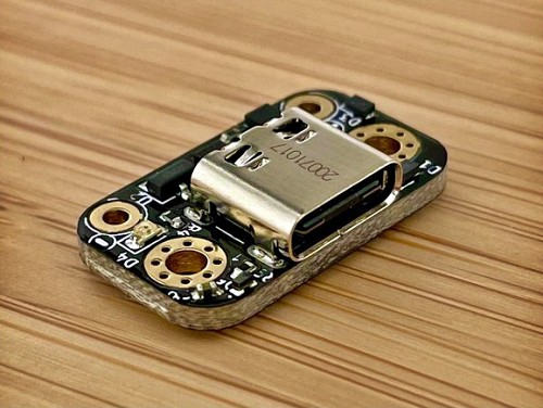
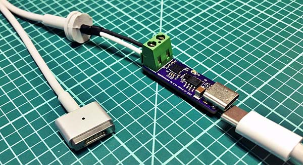
Nevertheless, if you want to try a few new things hardware-wise with this idea, go for bare chips like STUSB4500, CYPD3177-24LQXQ, etc. Below you can see a USB-C PD module designed around CYPD3177 (thanks to https://twitter.com/alvaroprieto).
Coffee break…
Oh, it’s time to take a short break from this long conversation. I’m dealing with this topic for the second time and I think it will be useful for you. Okay, that’s it for now, but wait for the time-bound updates!