This quick intro post tells you something about converting radio-control (RC) hobby servo pulse width modulation (PWM) signals to pulse position modulation (PPM) signals using commonly available systems and components.
At this time, you can see the two output signal formats of radio receivers for radio-controlled models. The traditional and most popular type of receiver signal is PWM, which usually requires one wire per channel. But PPM signaling is now getting more and more interesting because it can handle all channels on a single wire. So, often there’s a need arises to convert PWM to PPM efficiently.
Before you dive, I personally recommend you take a moment to look at this article (if you haven’t already) as it will help give a little background and understanding of radio-controlled boats and their design https://www.electronicsforu.com/electronics-projects/basic-guide-radio-controlled-boat-modelling
PWM vs PPM
As noted above, PWM stands for pulse width modulation and PPM stands for pulse position modulation. The PWM method employs data in the form of a varying pulse width but in PPM analog sample values determine the position of a narrow pulse relative to the clocking time.
Recall, PWM and PPM are two of the popular radio receiver protocols used to transport data from a radio receiver to a radio-controlled device – an RC hobby servo for example.
In PWM, each RC channel has its own signal cable whereas in PPM, multiple PWM signals are lined back to back and the same signaling is used but each channel is sent in turn, then it loops back to the first channel after a delay.
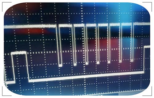
And in the PWM technique, the analog signal takes the form of a pulse, and the length of the pulse represents a specific value, with 1000 being the minimum, and 2000 being the maximum value. Since each PWM channel needs its own signal wire if you have an 8-channel setup you will need to connect 8 wires along with power supply wires to handle the signals. Simply, the PWM signal is a periodic square wave signal with a period of 20ms, thus a refresh frequency of 50Hz.
Of course, PPM is also an analog signal, but instead of employing a separate signal wire for each channel, PPM stacks each signal one after another to send them all along the same signal wire, and this obviously makes the overall wiring much easier. Simply put, the PPM signal is a signal modulated by putting multiple control channels together and thus can be regarded as a frame of data that holds several channels of information.
So, in brief, pulse width modulation in principle requires one signal wire per channel but pulse position modulation can handle many channels thru a single signal wire. That’s why PPM is now getting more and more attractive than PWM.
PWM to PPM
Sometimes you need to use a PWM to PPM converter in your RC model. Luckily, such converters/adapters/modules are available everywhere nowadays. So, you can quickly buy one from an online store or can build one yourself if you have enough skill and patience. Note, that it’s also easy to obtain PWM signals from PPM signals.
The basic design approach of PWM to PPM conversion is to detect the rising and falling edges of each PWM channel, generate PPM pulses from each edge, and then combine them into one PPM channel. Usually, such a clever setup can process anywhere from one to eight PWM channels.
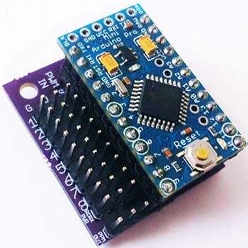
As an example, here you can see a fun project that uses an Arduino Pro Mini to convert PWM into PPM http://www.brokking.net/bain_pwm_to_ppm_for_r6b.html (I haven’t tested this idea yet).
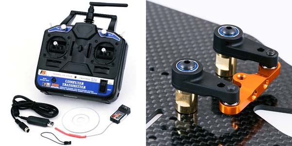
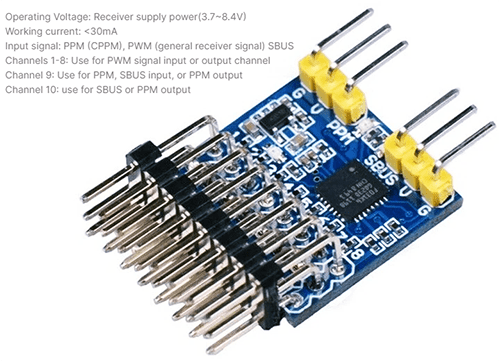
Until now, I have good faith in my soldering and circuit-building skills, but my extremely busy schedule often forces me to take dirty shortcuts (Not always dirty, I know). Anyway, I did a thorough search to find some PWM to PPM conversion modules and Google naturally returned an avalanche of surprising results. Below you can see the photograph of a Universal 8-Channel PWM/PPM/SBUS Signal Conversion Module.
Hey, What’s SBUS?
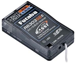
SBUS, introduced by Futaba (https://www.futaba.com/), as the name suggests, is a serial communication protocol. In addition to being a digital signal, the key advantage of SBUS is that it’s able to handle up to 18 channels using just one signal cable!
Since the SBUS is a digital signal, it offers higher resolution which means we’ve more precise control over our RC models. Moreover, SBUS is faster because of its low latency. In contrast, SBUS is a digital signal therefore calculations such as parity bits can be included with the signal to adjust for any possible interference which keeps the latency to a minimum.
You may check out this link to get a few more details about common RC TX/RX protocols http://www.pitch-play.nl/rc-tx-rx-protocols/
Get More!
Of course, I never like to stay in the theory phase so I recently bagged a vast range of RC hobby electronics components and devices to start a series of posts on related topics. Thus, you can see more useful practical things in later posts.

Next will be an entry-level hacking project to control some household appliances through a radio control transmitter and receiver (RC TX/RX) set. I hope I can touch it within a couple of weeks!