Introduction
Serial communication is the most widely used approach to transfer information between data processing equipment and peripherals. In general, communication means interchange of information between individuals through written documents, verbal words, audio and video lessons.
Every device might it be your Personal computer or mobile runs on serial protocol. The protocol is the secure and reliable form of communication having a set of rules addressed by the source host (sender) and destination host (receiver). To have a better insight, I have explained the concept of serial communication.
In embedded system, Serial communication is the way of exchanging data using different methods in the form of serial digital binary. Some of the well-known interfaces used for the data exchange are RS-232, RS-485, I2C, SPI etc.
What is Serial communication?
In serial communication, data is in the form of binary pulses. In other words, we can say Binary One represents a logic HIGH or 5 Volts, and zero represents a logic LOW or 0 Volts. Serial communication can take many forms depending on the type of transmission mode and data transfer. The transmission modes are classified as Simplex, Half Duplex, and Full Duplex. There will be a source (also known as a sender) and destination (also called a receiver) for each transmission mode.
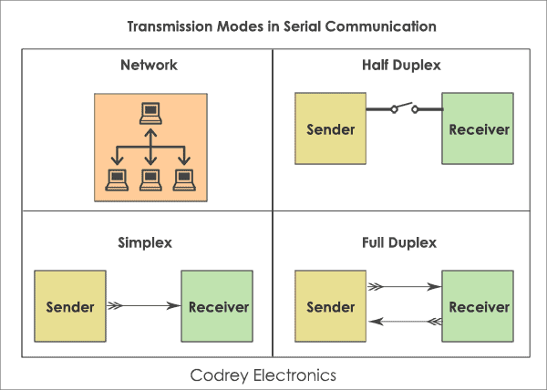
The Simplex method is a one-way communication technique. Only one client (either the sender or receiver is active at a time). If a sender transmits, the receiver can only accept. Radio and Television transmission are the examples of simplex mode.
In Half Duplex mode, both sender and receiver are active but not at a time, i.e. if a sender transmits, the receiver can accept but cannot send and vice versa. A good example is an internet. If a client (laptop) sends a request for a web page, the web server processes the application and sends back the information.
The Full Duplex mode is widely used communication in the world. Here both sender and receiver can transmit and receive at the same time. An example is your smartphone.
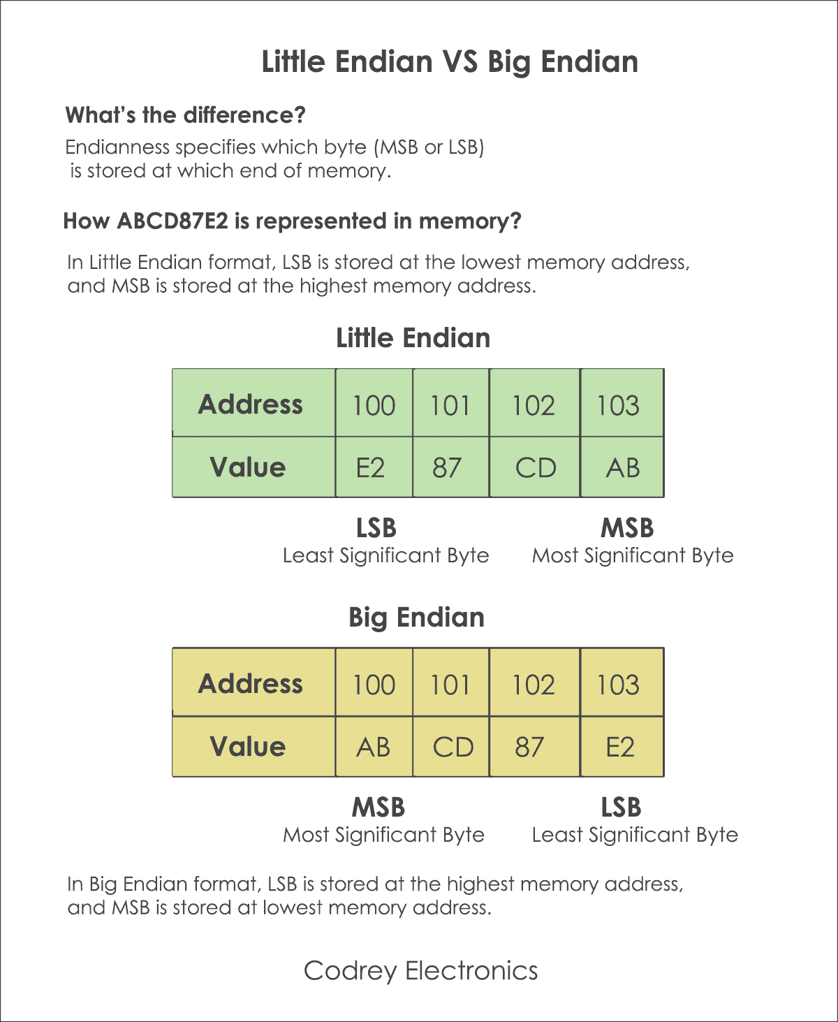
Beyond the transmission modes, we have to consider the endianness and protocol design of the host computer (sender or receiver). Endianness is the way of storing the data at a particular memory address. Depending on the data alignment endian is classified as
- Little Endian and
- Big Endian.
Take this example to understand the concept of endianness. Suppose, we have a 32-bit hexadecimal data ABCD87E2. How is this data stored in memory? To have a clear idea, I have explained the difference between Little Endian and Big Endian.
Data transfer can happen in two ways. They are serial communication and parallel communication. Serial communication is a technique used to send data bit by bit using a two-wires i.e. transmitter (sender) and receiver.
For example, I want to send an 8-bit binary data 11001110 from the transmitter to the receiver. But, which bit goes out first? Most Significant Bit – MSB (7th bit) or Least Significant Bit- LSB (0th Bit). We cannot say. Here I am considering LSB is moving first (for little Endian).
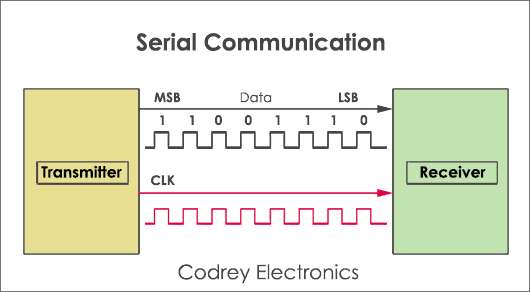
From the above diagram, for every clock pulse; the transmitter sends a single bit of data to the receiver.
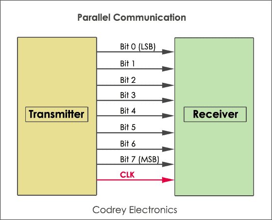
Parallel communication moves 8,16, or 32 bits of data at a time. Printers and Xerox machines use parallel communication for faster data transfer.
Difference between Serial and Parallel communication
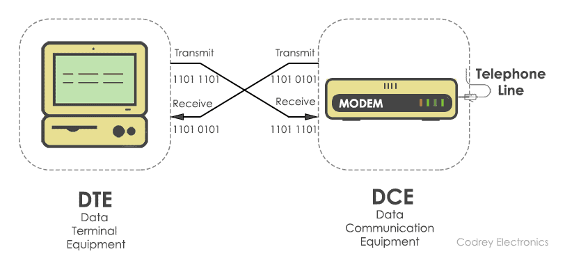
Serial communication sends only one bit at a time. so, these require fewer I/O (input-output) lines. Hence, occupying less space and more resistant to cross-talk. The main advantage of serial communication is, the cost of the entire embedded system becomes cheap and transmits the information over a long distance. Serial transfer is used in DCE (Data communication Equipment) devices like a modem.
In parallel communication, a chunk of data (8,16 or 32 bit) is sent at a time. So, each bit of data requires a separate physical I/O line. The advantage of parallel communication is it is fast but its drawback is it use more number of I/O (input-output) lines. Parallel transfer is used in PC (personal computer) for interconnecting CPU (central processing unit), RAM (random access memory), modems, audio, video and network hardware.
Note: If your Integrated Circuit or processor supports less amount of Input/Output pins it is better to opt serial communication
For easy understanding, here is the comparison of serial and parallel communication.
| Serial Communication | Parallel Communication |
|---|---|
| Sends data bit by bit at one clock pulse | Transfers a chunk of data at a time |
| Requires one wire to transmit the data | Requires ‘n’ number of lines for transmitting ‘n’ bits |
| Communication speed is slow | Communication speed is fast |
| Installation cost is low | Installation cost is high |
| Preferred for long distance communication | Used for short distance communication |
| Example: Computer to Computer | Computer to multi function printer |
Clock Synchronization
For efficient working of serial devices, the clock is the primary source. Malfunction of the clock may lead to unexpected results. The clock signal is different for each serial device, and it is categorized as synchronous protocol and asynchronous protocol.
Synchronous serial interface
All the devices on Synchronous serial interface use the single CPU bus to share both clock and data. Due to this fact, data transfer is faster. The advantage is there will be no mismatch in baud rate. Moreover, fewer I/O (input-output) lines are required to interface components. Examples are I2C, SPI etc.
Asynchronous serial interface
The asynchronous interface does not have an external clock signal, and it relies on four parameters namely
- Baud rate control
- Data flow control
- Transmission and reception control
- Error control.
Asynchronous protocols are suitable for stable communication. These are used for long distance applications. Examples of asynchronous protocols are RS-232, RS-422, and RS-485.
How Serial communication Works?
Advanced CPU such as microcontroller and Microprocessor make use of serial communication to communicate with the external world as well as on the chip peripherals. To get familiar, let us take a simple example. For suppose, you want to send a file present in your laptop to smartphone. How would you send? Probably using Bluetooth or WiFi protocol, Right.
So, here are the steps to establish the serial communication
- Add the connection.
In the first step, your laptop will search for devices nearby 100m and will list out the devices found. This process is often called roaming.
- Select the device you want to communicate.
To connect to your mobile, the pairing has to be done. The default configuration is already present in the software. So no need to configure the baud rate manually. Beyond this, there are four unknown rules. They are baud rate, data bit selection (framing), start-stop bit, and parity.

# 1 What is Baud rate?
Baud rate is the speed of transferring data from the transmitter to a receiver in the form of bits per second. Some of the standard baud rates are 1200, 2400, 4800, 9600, 57600.
You have to set the same baud rate on both sides (Mobile and Laptop).
Note: The Higher a baud rate, more data can be transferred in less amount of time.
However, I recommend using up to 115200 as a safe limit due to mismatch of sampling frequency at the receiver end.
# 2 Framing
Framing shows how many data bits you want to send from the host device (Laptop) to mobile (receiver). Is it 5, 6, 7, or 8 bits? Mostly many devices, 8 bits are preferred. After selecting the8-bit data chunk, endianness has to be agreed by the sender and receiver.
# 3 Synchronization
Transmitter appends synchronization bits (1 Start bit and 1 or 2 Stop bit) to the original data frame. Synchronization bits help the receiver to identify the start and end of the data transfer. This process is known as asynchronous data transfer.
# 4 Error Control
Data corruption may happen due to external noise at the receiver end. The only solution to get the stable output is to check the Parity.
If the binary data contains an even number of 1’s it is known as even parity and the Parity bit is set to ‘1’. If the binary data include an odd number of 1’s, it is called odd parity, and now parity bit is set to ‘0’.
Asynchronous Serial Protocols
The most common question that will come to mind when you start working on the embedded system is why to use Asynchronous protocols?
- To move around the information at a longer distance and
- For more reliable data transfer.
Some of the asynchronous communication protocols are:
RS-232 protocol
- RS232 is the first serial protocol used for connecting modems for telephony. RS stands for Recommended Standard, and now it has changed to EIA (Electronic Industries Alliance ) / TIA ( Telecommunication Industry Association).
- It is also used in modem, mouse, and CNC (computed numerical computing) machines. You can connect only a single transmitter to a single receiver.
- It supports full duplex communication and allows baud rate up to 1Mbps.
- Cable length is limited to 50 feet.
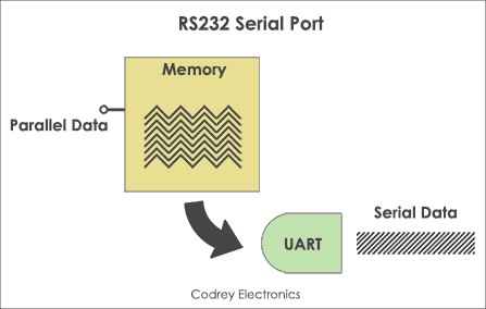
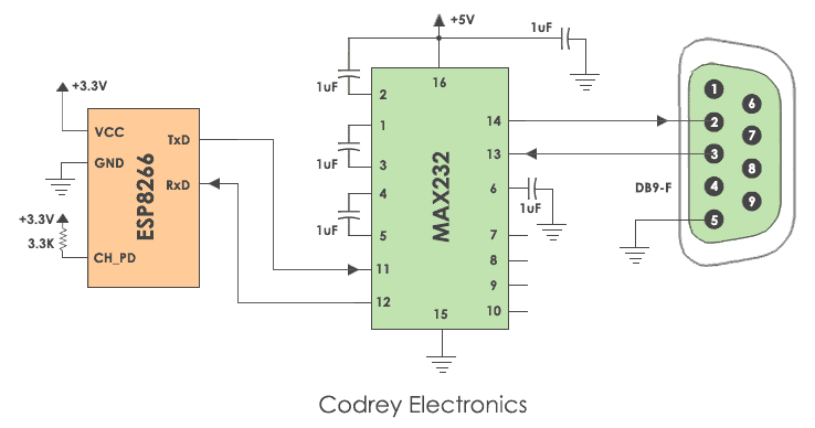
As you know, the data stored in the memory are in the form of bytes. You may have a doubt How is the byte-wise data converted to binary bits? The answer is a Serial port.
The serial port has an internal chip called UART. UART is an acronym for Universal Asynchronous Receiver Transmitter which converts the parallel data (byte) into the bitwise serial form.
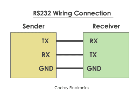
RS-232 Wiring Connection
The RS232 serial port has nine pins, male or female type models. RS 232C serial communication interface is the later version of RS232.
All the features present in RS232 is present in the RS232C model except it has 25 pins. Out of 25 or 9 pins, we use only three pins for the connection of terminal devices.
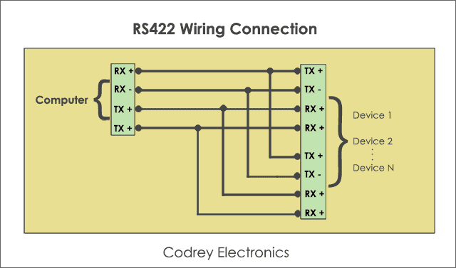
RS422 Interface
We can transfer data only up to 1Mpbs limit using RS232. To overcome this problem RS422 comes into the picture. RS422 is a multi-drop serial interface. we can connect ten transmitters to 10 receivers at a time using the single bus. It sends data using two twisted pair cables ( differential configuration). Cable length is 4000 feet with a baud rate of 10Mbps.
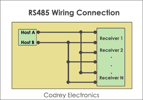
RS485 Interface
RS485 is the industry preferred protocol. Unlike RS422, you can connect 32 line drivers and 32 receivers in a differential configuration. The transmitter is also called Line driver. However, only one transmitter is active at a time.
Note: For both RS232 and RS485, you have to terminate the connection manually.
1-Wire Protocol
One wire is similar to I2c protocol. But, the difference is one wire protocol uses single data line and ground. It requires no clock signal and the slaves are clocked using internal crystal oscillator. It provides half duplex communication.
One wire uses 64-bit addressing scheme. The advantage of one wire interface is, it supports long distance communication with low cost. But, the disadvantage is its speed is less.
Asynchronous wired protocols are well suited for long distance communication. However, there is one drawback giving scope to synchronous serial interfaces.
The drawback is, if there is a need to connect more transmitters and receivers the installation cost goes high.
Synchronous Serial Protocols
Synchronous communication protocols are the best resources for onboard peripherals. The advantage is you can interface more devices on the same bus. Some of the synchronous protocols are I2C, SPI, CAN, and LIN.
I2C Protocol
I2c (Inter-integrated circuit) is a two-wire bidirectional protocol used for an exchange of data between different devices on the same bus. I2c uses 7 bit or 10-bit address allowing to connect up to 1024 devices. But, it requires clock signal for generating start and stop conditions. The advantage is it provides data transfer at 400 kbps. It is suitable for onboard communication.
SPI Protocol
SPI (Serial peripheral interface) protocol send and receive data in a continuous stream without any interruption. This protocol is recommended for highspeed data communication is required. The maximum speed it can provide is 10 Mbps.
Unlike i2c, SPI has 4 wires. They are MOSI (Master out slave in), MISO (Master in slave out), Clock and Slave select signal. Theoretically, we can connect unlimited number of slaves and practically it depends on the load capacitance of the bus.
CAN Protocol
This protocol is dedicated to vehicle systems or automobiles. It is a message-oriented protocol used for multiplex electric wiring to economize the copper. It is a multi-master multi serial bus used in applications such as automatic start/stop of vehicles, collision avoidance systems etc.
USB
USB interface is the best alternative to serial or parallel ports. The data transfer associated with USB ports are quite faster than the serial and parallel interface. USB supports speeds from 1.5 Mbps (USB 1.0) to 4.8 Gbps (USB 3.0). Today most of the embedded devices use USB OTG (On the Go programming) technique for dumping the hex file to the microcontroller.
Microwire
Microwire is a three wire serial communication protocol. It has a serial I/O port on the microcontroller to interface with peripheral chips. It supports speed up to 3Mbps. It faster than i2c and subset of SPI protocol.
Conclusion
Serial Communication is the vital part in the area of Electronics and Embedded Systems. The rate of data transfer is critical if two devices want to exchange information on the same bus. Hence, it is necessary to choose a valid serial protocol for any application.
Also read: What is Embedded System and How it Works?
[no_toc]
Very helpful thank you!
To be honest a lot of information neatly tied into one article, I had several tabs open to get the full picture this article presents
Great article, Well done and thank you for sharing 🙂
Thanks for the detailed information. Would it be more better if comparison of languages used for serial communication is explained as well? Thank you.
Nice Article for beginner who want to get started in embedded field.
Please share some more in depth article related to modbus protocol and all protocols used.
How the protocols works practically in real life?
it is Good and Easy understanding with example