UART (Universal Asynchronous Transmitter Receiver), this is the most common protocol used for full-duplex serial communication. It is a single LSI (large-scale integration) chip designed to perform asynchronous communication. This device sends and receives data from one system to another system.
In this tutorial, you will learn the basics of UART communication, and the working of the UART.
What is UART?
“UART” stands for Universal Asynchronous receiver-transmitter. It is a hardware peripheral that is present inside a microcontroller. The function of UART is to convert the incoming and outgoing data into the serial binary stream. An 8-bit serial data received from the peripheral device is converted into the parallel form using serial to parallel conversion and parallel data received from the CPU is converted using serial to parallel conversion. This data is present in modulating form and transmits at a defined baud rate.
Why UART is used?
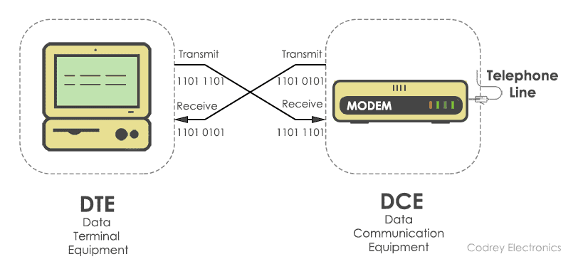
Protocols like SPI (serial peripheral interface) and USB (Universal Serial Bus) are used for fast communication. When the high-speed data transfer is not required UART is used. It is a cheap communication device with a single transmitter/receiver. It requires a single wire for transmitting the data and another wire for receiving.
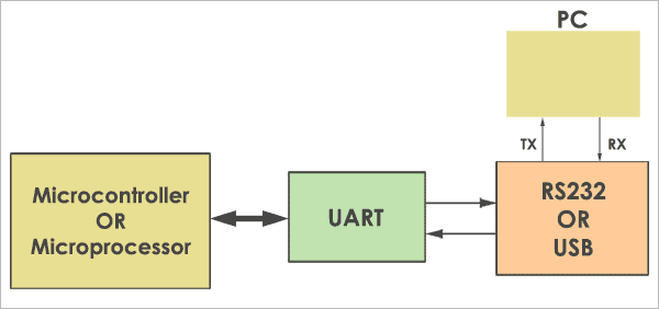
It can be interfaced with a PC (personal computer) using an RS232-TTL converter or USB-TTL converter. The common thing between RS232 and UART is they both don’t require a clock to transmit and receive data. The Uart frame consists of 1 start bit, 1 or 2 stop bits and a parity bit for serial data transfer.
Block Diagram
The UART consists of the following core components. They are the transmitter and receiver. The transmitter consists of the Transmit hold register, Transmit shift register, and control logic. Similarly, the receiver consists of a Receive hold register, Receiver shift register, and control logic. In common, both the transmitter and receiver are provided with a baud rate generator.
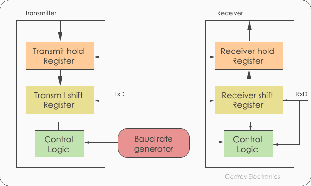
The baud rate generator generates the speed at which the transmitter and receiver have to send/receive the data. The Transmit hold register contains the data byte to be transmitted. The transmit shift register and receiver shift register shift the bits to the left or right until a byte of data is sent/received.
In addition to these, a read or write control logic is provided to tell when to read/write. The baud rate generator generates speeds ranging from 110 bps (bits per second) to 230400. Mostly, microcontrollers come up with higher baud rates such as 115200 and 57600 for faster data transfer. Devices like GPS and GSM use slower baud rates in 4800 and 9600.
How UART works?
To know the working of UART, you need to understand the basic functionality of serial communication. In short, transmitter and receiver use start bit, stop bit, and timing parameters to synchronize with each other. The original data is in parallel form. For example, we have 4-bit data, to convert it into the serial form, we need a parallel to serial converter. Generally, D flip-flops or latches are used to design the converters.
Working of D – Flip-flop
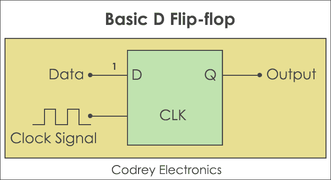
D flip-flop also known as Data flip-flop shifts one bit from the input side to the output side if and only, when the clock changes the transition from a high state to a low state or low state to a high state. Likewise, if you want to transfer four bits of data you need 4 flip-flops.
Note: Here,
‘D‘ represents input data.
‘CLK‘ indicates clock pulses.
‘Q‘ denotes output data. Now, let’s design a parallel to serial and serial to parallel converter.
Parallel to Serial Conversion
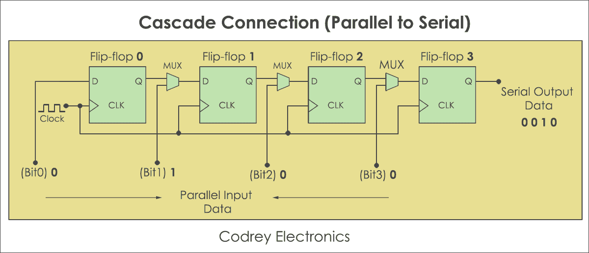
Step#1:
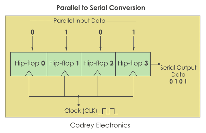
Take 4 Flip-flops. The number of flip-flops is equivalent to the number of bits to be transmitted. Similarly, put Multiplexers in front of each flip-flop, but excluding the first one. A multiplexer is placed to combine the data and convert it to serial bits. It has two inputs, one parallel bit data and another from the previous flip-flop.
Step#2:
Now, Load the data at a time in the D flip-flops. It will pull the parallel data and moves the last bit of last flip-flop (four), and then the third bit, second bit, and finally the first bit. Now, to reconvert the parallel data into serial form serial to parallel converter is used.
Serial to Parallel Conversion
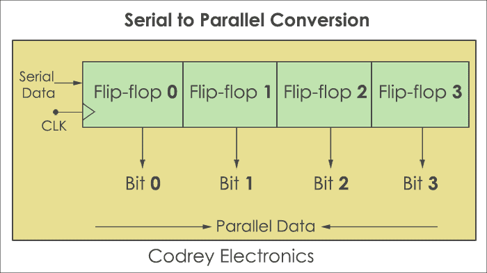
Step#1:
Take 4 Flip-flops. The number of flip-flops is the same as the number of bits to be transmitted.
Step#2:
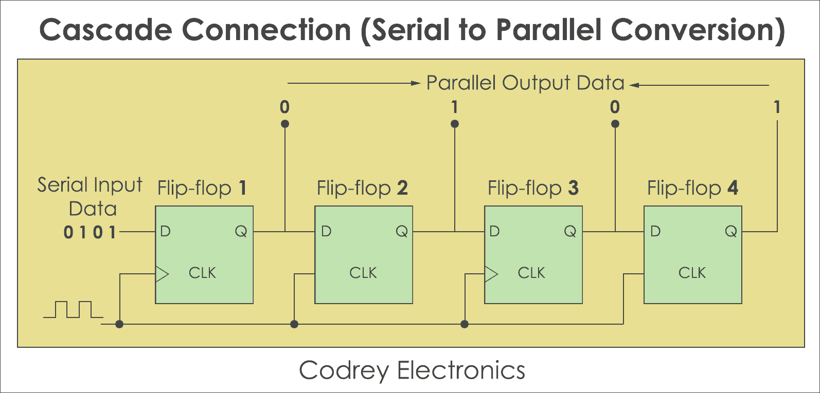
Initially, disable the parallel bus. Don’t enable until all bits are loaded. Store the data at the input of the first flip-flop. Now make clock high, this will shift the least significant bit to the input of the second flip-flop and the output of the first one. Similarly, shift all the bits one by one by making the clock pulse high. The converter is in the hold state until all bits are transferred to the output.
Step#3:
Now each flip-flop contains one bit of serial data. Erstwhile all bits are transferred to the flip-flop output, enable the bus. This will make the converter to send all the bits at a time.
Protocol Format
The UART starts the communication with a start bit ‘0’. The start bit initiates the transfer of serial data and stop bit ends the data transaction.
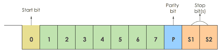
It is also provided with a parity bit (even or odd). Even parity bit is represented by ‘0’ (even number of 1’s) and the odd parity bit is represented by ‘1’ (odd number of 1’s).
Transmission
The transmission of data is done using a single transmission line (TxD). Here ‘0’ is considered as space and ‘1’ is known as mark state.
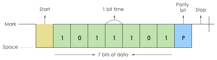
The transmitter sends a single bit at a time. After sending one bit, the next bit is sent. In this way, all the data bits are sent to the receiver with a predefined baud rate. There will be a certain delay in transmitting each bit. For example, to send one byte of data at 9600 baud rate, each bit is sent at 108 µsec delay. The data is added with a parity bit. So, 10 bits of data are required to send 7 bits of data.
Note: In transmission, always LSB (Least Significant Bit) is sent first.
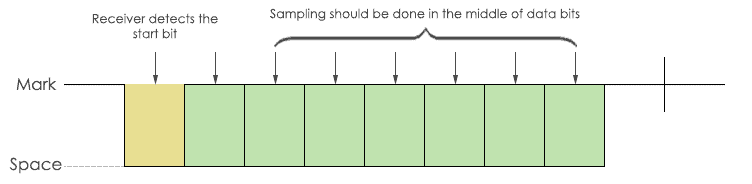
Reception
During the reception, the RxD line (Receiver) is used for receiving the data.
Example of UART interfacing
This example demonstrates the interfacing of ESP8266 UART with MAX232. But, before I jump into the details of interfacing, let me share the pin details of the Max232 driver.
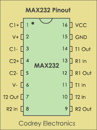
MAX232 IC is powered up by 5V supply which includes a capacitive voltage generator to drive 232 level voltages. It comes with dual transmitters also called the driver (TIN, TOUT) and receivers (RIN and ROUT).
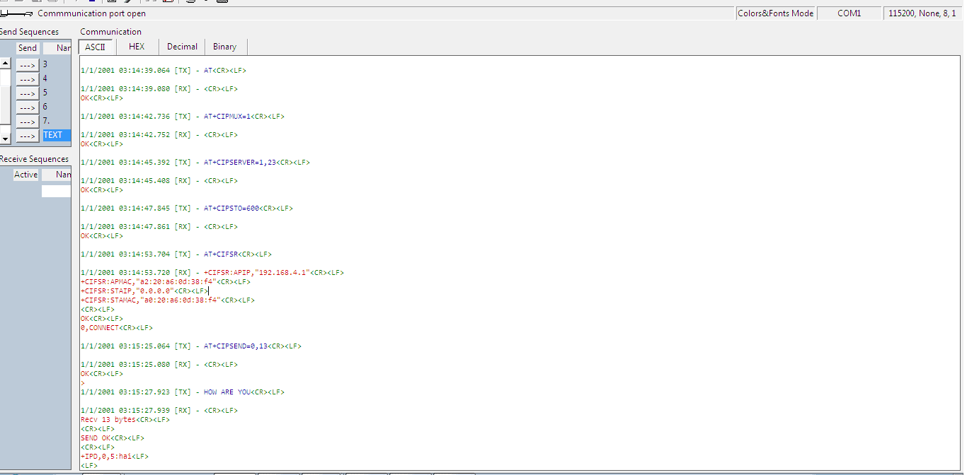
Here, I have used ESP8266 (32-bit microcontroller) which has inbuilt UART. The communication can be done with ESP8266 using AT commands via RS232 to TTL level converter (MAX232). The below figure shows the connection of ESP8266 with PC (personal computer).
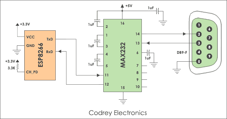
By requesting valid AT commands through the PC the Wi-Fi chip will respond with an acknowledgement. I don’t want to go in-depth about ESP8266 and it will be explained in the future tutorials.
Here are the steps to implement serial communication with PC.
- Connect Transmitter (TX) of ESP8266 to Receiver (TX) of RS232 to TTL level converter (MAX232) and RX of PC.
- Connect Receiver (RX) of ESP8266 to TX of PC and RX of TTL converter.
ESP8266 Commands
| AT command (Sent from PC) | ESP8266 Response (received by PC) |
|---|---|
| AT<CR><LF> | OK<CR><LF> |
| AT+CIPMUX=1 | OK<CR><LF> |
| AT+CIPSERVER=1,23<CR><LF> | OK<CR><LF> |
The below screenshot shows the response given by the ESP8266 module.
UART vs USART
USART is the basic form of UART. Technically, they are not the same. But, the definition is the same for both of them. These are microcontroller peripherals that convert parallel data into serial bits and vice versa.
The main difference between UART and USART is, UART supports only asynchronous communication, whereas USART support synchronous as well as asynchronous communication. For easy understanding, here is the comparison between USART and UART.
| UART | USART |
|---|---|
| The Clock is generated internally by the microcontroller. | The sending device will generate the clock. |
| The data rate is slow. | The data rate is higher due to external clock. |
| Standalone protocol | Supports multiple protocols like LIN, RS-485, IrDA, Smart Card etc. |
| The baud rate should be known before transmission. | No need to know the baud rate earlier. |
| Suitable for low speed communications | Suitable for high speed communications. |
| Reduced energy footprint. | Handles serial communication during high energy consumption |
RS232 and UART
Logic levels represent the operating voltage levels that a device can withstand to operate in a safe zone. Here are the voltage levels for RS232 and TTL.
RS232 Logic:
RS232 Voltage Levels
| Logic Level | Voltage Range |
|---|---|
| Logic High or OFF output | -5V to -15V |
| Logic Low or ON output | +5V to +15V |
| Logic High or OFF input | -3V to -15V |
| Logic Low or ON input | +3V to +15V |
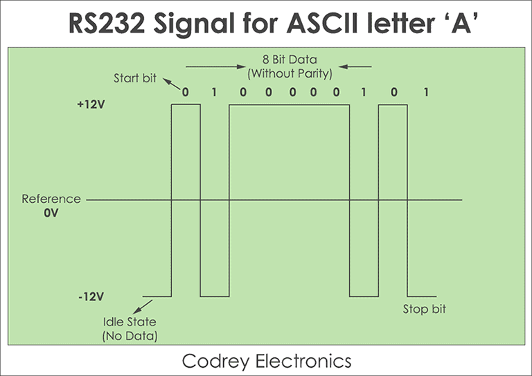
In most cases RS232 levels range from -12V to +12V. For instance, an ASCII value for a character ‘A‘ in RS232 is 65 and 41 in Hexadecimal. So in an 8-bit binary format, it is 0100 0001. The RS232 signals are represented as inverted logic. Logic level ‘0’ is shown as ‘1’ and Logic level ‘1’ is shown as ‘0’. The data transmission of RS232 begins with a start bit (0) followed by 8 data bits (LSB first) and a stop bit.
Here shows the representation of RS232 logic levels for ASCII ‘A‘.
TTL/CMOS Logic:
The UART works on TTL logic. The voltage level of TTL ranges from 0 to 5V, represented with no inversion.
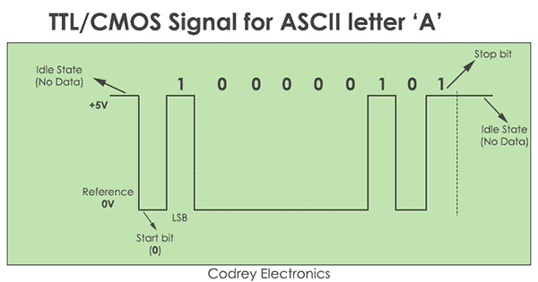
- Initially, the serial line is in the idle state commonly called a Mark state (Logic 1). Now, the data transmission begins with a start bit (logic 0).
- Further, eight data bits are sent over the serial line one after another with LSB (Least significant bit) first.
- After the entire transmission is over, a stop bit (logic 1) is encountered.
Advantages
The advantage of UART is, it supports full-duplex communication using two wires. Also, it requires no external clock for data communication. It supports error checking using a parity bit and the length of the data can be changed easily.
Disadvantages
The major disadvantage of UART is, it doesn’t support multi-slave or multi-master configuration. And, the size of the data packet is limited to 9 bits. The UART is not suitable for heavy lifting serial communication during high energy consumption.
Applications
- Serial debug port uses the UART driver to print out the data coming from the external world.
- We can use it to send and receive commands to and from the embedded devices.
- Communication in GPS, GSM/GPRS modem, Wi-Fi chips, etc operates with UART.
- Used in Mainframe access to connect different computers.
This is helpful matter…
Can MAX232 be used to convert USB to TTL
Hi Neeraj,
Glad to note your comments.Thanks.
MAX232 IC is recommended to interface with RS232 devices having DB9 ports. If you want to use USB interface you can use FT232RL or PL2303 USB to serial interface IC’s based on your requirement.
Can I use your images in my diploma thesis?
Hi Daniel,
Yes, you can use it for personal use.
Thank you.