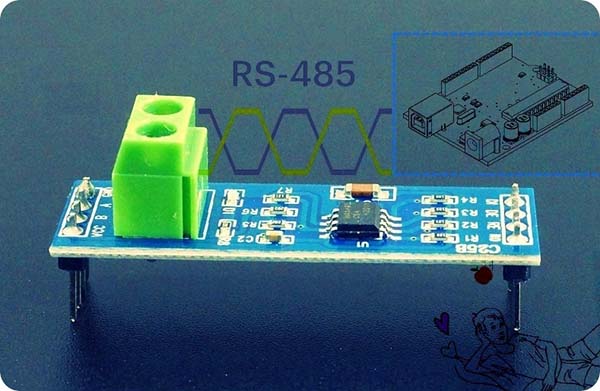
 RS-485 is a standard serial protocol, with bus topology where you can connect several devices in a very cheap and cheerful way. Here will be explained how to begin your Arduino + RS-485 projects. Okay, get ready to get started!
RS-485?
First off, note that RS-485, also known as TIA-485(-A) or EIA-485, does not define a communication protocol – it’s simply an electrical interface, but very similar to the quite familiar RS-232. However, RS-485 improves upon RS-232 by removing the restriction of distance and helps more than two devices to communicate using a single line, though it does this at the cost of using more wires between the devices.
There are many reasons why you may need an RS-485 bus. Just imagine that you have a bunch of devices installed far away from each other. In such a case, RS-232 (or TTL serial) is not practicable because the cables are too long, the signal is damped and data cannot be handled efficiently. However, with an RS-485 bus it is possible to use a cable length up to 1200 meters (with a data transmission speed of 100 kbit/s).
The RS-485 bus usually uses two wires (+/-) and this configuration (a differential couple of wires) allows to employ it in half-duplex mode. With a four-wire configuration, an RS-485 bus is able to work in full-duplex mode, that approach has certain inherent limitations though.
Now we know that RS-485 (https://en.wikipedia.org/wiki/RS-485) is a half-duplex communication electrical interface that uses differential signaling (https://en.wikipedia.org/wiki/Differential_signaling) over a pair of wires. And, it allows a bus topology with multiple nodes connected to the same wire pair (only one node at a time is allowed to drive the bus, while the other nodes must be in reception mode).
At this time, it’s worthy to notice that although many applications use RS-485 signal levels, the speed, format, and protocol of the data transmission are not specified by RS-485. Besides, RS-485 does not specify any connector or pinout. Circuits may be terminated on screw terminals or other types of connectors.
RS-485 + Arduino?
Even though Arduino supports serial communication through its built-in UART, it uses TTL, not RS-485. Both signaling types use serial communication, but TTL is single-ended, whereas RS-485 relies on a differential signal. Therefore, in order to allow an Arduino to talk over an RS-485 network, an additional device must be used to convert TTL to RS-485.
There are several ICs on the market that do this, and the easiest and inexpensive one is the MAX485 (https://datasheets.maximintegrated.com/en/ds/MAX1487-MAX491.pdf).
The MAX485 IC is a half-duplex transceiver that meets the specifications of RS-485 and RS-422. This IC is commonly available in DIP-8 and SOP-8 packages and meets the requirements of the RS-485 and RS-422 protocols up to 5Mbps underload. Below is its pin configuration, logic diagram, and truth table, taken directly from an HTC datasheet (Apr. 2019_R1.1).
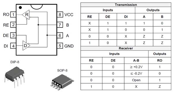
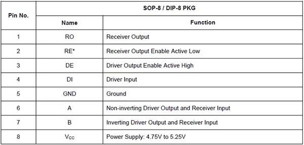
Here’s its pin description:
MAX485 TTL to RS-485 Module
Arduinos are usually confined to hobbyist and educational markets for prototyping because of their low barrier to entry. If you’ve a low-profile project that could use MAX485 chips, then a better idea is to use a MAX485 breakout board or module as it’s comparatively cheap and easy to use with Arduino boards (and most other microcontrollers). I already got a few modules from a neighbouring webstore for an incredibly low price!
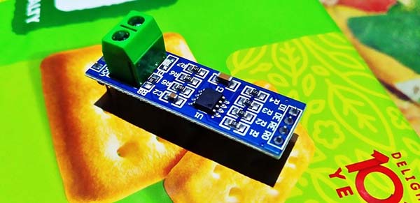
The “MAX485 TTL to RS-485 Interface Module” allows microcontrollers to use the RS-485 differential signaling for robust long-distance serial communications over long distances of up to 4000 feet even in electrically noisy environments. The module has two 4-pin headers and a tw0-wire screw terminal block.
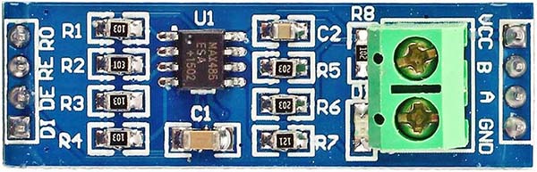
Now to the module connections:
1 x 4 Header (Left side)
- RO = Receiver Output
- RE = Receiver Enable – Active LOW
- DE = Driver Enable – Active HIGH
- DI = Driver Input
1 x 4 Header (Right side)
- VCC = 5V
- B = Data ‘B’ Inverted Line
- A = Data ‘A’ Non-Inverted Line
- GND = Ground
1 x 2 Screw Terminal Block
- B = Data ‘B’ Inverted Line
- A = Data ‘A’ Non-Inverted Line
The module provides four 10K pull-up resistors (R1-R4) on the data lines. Also, there are two 20K resistors (R5-R6) on the A/B differential lines. Finally, there’s a single 120Ω resistor. This “termination” resistor (R7) goes between the A/B differential lines on each end of the cable to prevent reflections.
Strike a note, the trickiest part when working with these modules is to ensure that the DE/RE lines are held in the correct state!
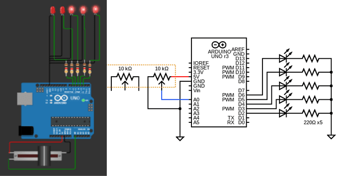
Below you can see the basic schematic.
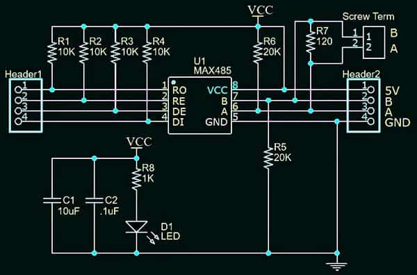
In this module, the positive line is called A (Pulled-up to VCC), while the negative line is called B (Pulled-down to GND). Note also that the 120 termination resistor is generally a good inclusion as you can use a pair of these pretty simple modules to implement a point-to-point connection. But see, in some projects you may need to remove it. For example, if your module resides in the middle of the bus, it’s a middle node indeed, thus it should not have the termination resistor (but the modules on the two ends of the line should keep the termination resistor).
Overview – RS232, RS423, RS422, and RS485
Line drivers and receivers are commonly used to exchange data between two or more points nodes on a network.
Electronic data communications between nodes will generally fall into two broad categories – single-ended and differential. However, when communicating at high data rates (or over long distances), single-ended methods are often inadequate. Differential data transmission offers superior performance in most applications because differential signals can help nullify the effects of ground shifts and induced noise signals that can appear as common mode voltages on a network.
Quick reference for RS232, RS423, RS422, and RS485 – http://www.rs485.com/rs485spec.html
Introduction – Modbus
Modbus is a data communications protocol originally published by Modicon in 1979 for use with its programmable logic controllers (PLCs).
Modbus has become a de facto standard communication protocol and is now a commonly available means of connecting industrial electronic devices. The Modbus protocol uses character serial communication lines, Ethernet, or the Internet protocol suite as a transport layer, and is often used to connect a plant/system supervisory computer with a remote terminal unit (RTU) in Supervisory Control and Data Acquisition (SCADA) systems in the electric power industry.
More on Modbus https://en.wikipedia.org/wiki/Modbus
Modbus Protocol Description https://www.modbustools.com/modbus.html
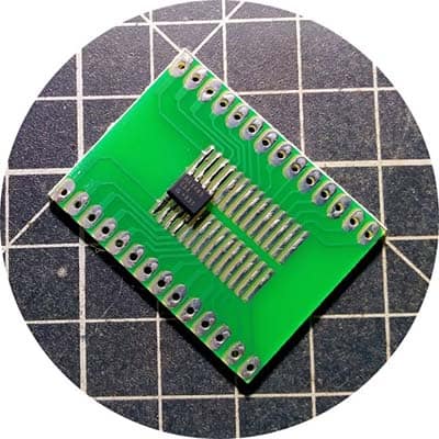
An Arduino could be a budget device in a MODBUS network, and the MAX485 IC or MAX485 module is cheap enough that it’s a small price-of-entry to experimenting with MODBUS on the Arduino. I also made some MAX485 (SOP-8) breakout boards for quick tests (see below).
The Next Thing…
Now I’m digging into how differential communication for LED lighting systems work. And, I’m hoping to get some ideas to build an entry-level Pixel LED controller as I wasn’t able to find any adaptable ones for what I wanted. A future post will show how I rigged up that RS-485 + Arduino Pixel LED system myself!
![]()
Finally, I haven’t gotten around to building a practical project using MAX485 yet (but you can do a lot with it). Hopefully, I’ve explained it well enough so you can have a stab at it. If you’re feeling really stuck, give me a shout in the comments below.
Thanks for your insightful explanation of the RS485. I have been thrown into the realm by my desire to integrate an ultrasonic wind sensor onto lorawan via arduino, where the said sensor unfortunately only outputs RS485. While out of my depth I am collecting the parts that will hopefully enable this, (max485 rs485, Heltec CubeCell; renkeer.com/product/ultrasonic-anemometer). Hopefully I will muddle my way through patching that onto my lorawan gateway.
Anthony Hill: Thanks for the inspiring comment. Glad to read about your project idea. Hope you will share more about the project status with us in due course. All the best!
Good explaination based on knowledge and experieince. Observing max circuit is heating in our pcb although pull up resistors as 10K but A/B line pull up and pull down are also 10k. Can you share what could be reason for heating, Regards
@Tomar: This is common, and based on my limited experience, the cause of the overheating problem could be one (or more) of the following:
1. Transient noises and spikes in the power supply rails
2. Lack of a common GND connection
3. Frequent common mode transient voltages between A, B and GND (especially when used in a very noisy environment)
4. Improper termination
5. Counterfeit ICs
If you get a successful solution with something not mentioned here, please drop a comment below so that it will help others. Thanks!